
Why Phase-Stable RF Cable Assemblies Are Critical for Aerospace Applications
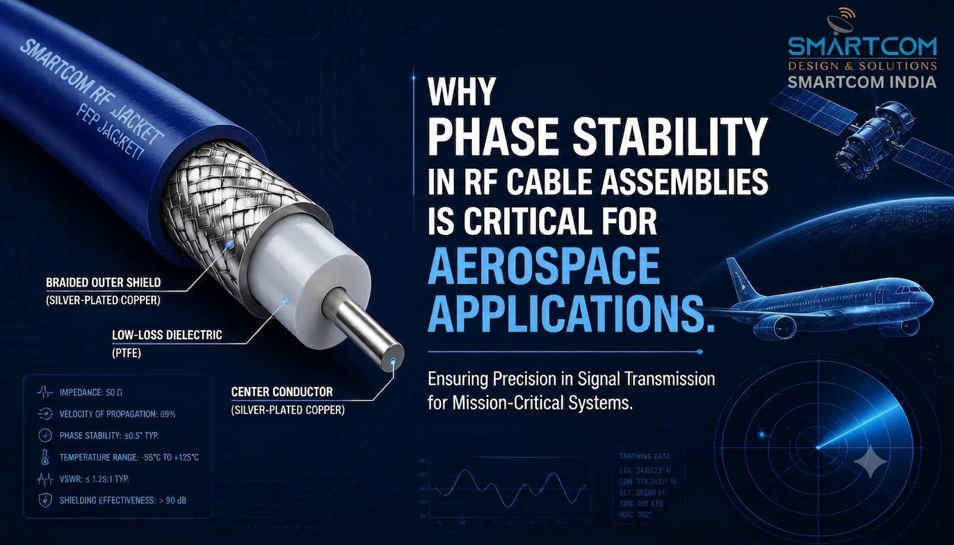
In aerospace and space systems, RF cable assemblies serve as essential components of the measurement and signal path. In high-precision environments, even minor changes in electrical length can significantly impact phase-sensitive applications.
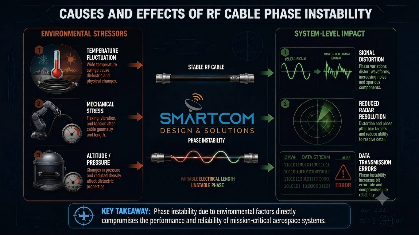
Aircraft, satellites, radar platforms, EW systems, navigation equipment, and RF test platforms expose cable assemblies to thermal swings, vibration, mechanical movement, repeated flexing, and challenging installation conditions. These stressors can cause conventional cables to experience phase changes due to variations in physical geometry and dielectric properties.
High-performance, phase-stable cable assemblies are essential for applications requiring consistent electrical length and repeatable RF performance.
Looking for high-frequency coaxial assemblies built to your exact specifications? Reach out to Smartcom India and let’s discuss your project goals.
Key Takeaways
- Core Definition: Phase stability measures how consistently an RF cable assembly maintains its electrical phase across changing environmental and mechanical conditions.
- Primary Stressors: Temperature fluctuations and mechanical movement can alter a cable’s physical dimensions and dielectric properties, modifying its effective electrical length.
- Geometric Distortion: Dynamic flexure can change cable geometry and influence RF phase stability.
- Operational Demands: Aerospace RF cable assemblies may need to maintain stable performance despite thermal cycling, vibration, tight routing, and mechanical stress.
- Holistic Evaluation: Evaluate phase stability in RF cables alongside insertion loss, Voltage Standing Wave Ratio (VSWR), electromagnetic shielding effectiveness, environmental resilience, and mechanical durability.
- Phase Matching vs. Phase Stability: Phase-matched cable assemblies are important when multiple RF channels must maintain a controlled phase relationship relative to one another.
- Application-Driven Selection: Selecting the appropriate cable construction depends on operating frequency, temperature range, mechanical constraints, routing profiles, and broader system architecture.
For a broader guide on signal integrity, cable architecture, and connector selection, explore Smartcom’s comprehensive overview: RF Coaxial Cables and Connectors: A Complete Guide to Signal Integrity.
What Is Phase Stability in an RF Cable Assembly?
Phase stability is a cable assembly’s ability to maintain a predictable and repeatable phase response during mechanical flexing or environmental changes.
As an RF signal travels through a coaxial cable, it encounters a propagation delay. The phase shift observed at the output connector depends on signal frequency, physical cable length, and the dielectric properties of the internal insulation.
This relationship can be expressed as:
Phase Shift = 360° × Frequency × Propagation Delay
Any change in propagation delay results in a corresponding phase shift.
Key Causes of Phase Shifts
- Physical length variations from thermal expansion or contraction
- Temperature-induced changes in dielectric properties
- Conductor geometry variations
- Ambient and internal operating temperature changes
- Mechanical flexing, bending, or twisting
- Structural compression or stretching during routing
- Connector interface movement
- Variations in internal cable manufacturing tolerances
At microwave and millimetre-wave frequencies, small changes in cable geometry or electrical length can cause measurable phase shifts. This is especially important in phase-sensitive applications that require precise signal relationships.
Why Does Phase Stability Matter in Aerospace?
Aerospace RF systems operate in environments with temperature fluctuations, vibration, mechanical movement, and space constraints, creating demanding conditions for RF interconnects.
Precision RF cable assemblies serve as critical links between components such as:
- Antennas and receivers
- Active electronically scanned array (AESA) radar modules
- Electronic warfare and signal intelligence (SIGINT) suites
- Global navigation satellite systems (GNSS)
- High-speed communications equipment
- Microwave modules and RF sensor payloads
- Onboard and benchtop RF test equipment
If the electrical phase of one signal path shifts relative to another, the system’s timing and phase relationships can be compromised. This is critical for systems relying on phase comparison, beamforming, delay-line calibration, or synchronous signal processing.
For example, phased-array antennas depend on controlled phase relationships across multiple channels. If individual signal paths undergo different phase changes due to temperature or mechanical stress, beamforming accuracy may decrease.
The impact extends beyond signal loss. In phase-sensitive architectures, phase changes can affect the accuracy of signal processing, steering, comparison, or synthesis.
How Temperature Impacts RF Cable Phase
Temperature significantly affects RF phase stability. Since coaxial cable assemblies use materials with different thermal properties, temperature changes can cause dimensional shifts and alter dielectric properties.
1. Thermal Expansion and Contraction
As temperature changes, the metal conductors, dielectric structure, and shielding components can expand or contract. At microwave and millimetre-wave frequencies, relatively small changes in physical dimensions or electrical length can produce measurable phase changes.
2. Dielectric Variation
The dielectric material surrounding the centre conductor influences signal propagation velocity. As temperature changes, the material’s dielectric properties can also change, affecting phase velocity and the assembly’s effective electrical length.
Specifying Thermal Stability for Aerospace
For aerospace applications, evaluating cables solely on thermal survival is insufficient. Engineers should assess low phase drift cable assemblies across the full operating temperature range, considering:
- Phase change over temperature according to the applicable measurement method
- Insertion-loss stability over temperature
- VSWR stability
- Mechanical durability and connector interface integrity
- EMI shielding effectiveness according to system requirements
Specialised aerospace cable assemblies can use carefully engineered dielectric and mechanical constructions designed to minimise phase drift across the required temperature range.
How Mechanical Flexing Alters RF Phase
Mechanical movement introduces additional variables into RF performance. Bending, twisting, compressing, or pulling a coaxial cable can alter its internal geometry.
Effects of Mechanical Stress
Mechanical stress can contribute to:
- Changes in effective electrical length
- Localised variations in characteristic impedance, typically 50 Ω
- Changes in propagation velocity
- Changes in insertion loss, return loss, and VSWR
- Phase drift during movement
Cables intended for static installations may not suit applications with repeated dynamic movement. Proper selection of phase-stable RF cable assemblies is important for applications such as:
- Gimballed antenna positioning systems
- Aircraft wing-to-fuselage pass-throughs
- Articulated avionics bay connections
- Automated test equipment (ATE) and portable RF instrumentation
- Flight-line maintenance interconnects
Specialised assemblies use engineered dielectric, shielding, and jacketing to minimise changes in electrical length during thermal variation and mechanical flexure.
Phase Stability vs. Phase Matching: Understanding the Difference
Phase stability and phase matching are distinct performance characteristics in RF cable assemblies for aerospace applications, though they are often discussed together.
Feature | Phase Stability | Phase Matching |
Definition | How consistently a single assembly maintains its phase when exposed to environmental or mechanical changes | How closely the electrical lengths or delays of two or more assemblies match under a defined condition |
Focus | Performance under changing operating conditions | Relative relationship between multiple signal channels |
Primary Goal | Minimize phase drift caused by temperature, flexure, or other specified conditions | Maintain a controlled channel-to-channel phase or delay relationship |
Why the Distinction Matters
An assembly may have good phase stability over temperature without being phase-matched to adjacent cables. Conversely, matched assemblies can meet a specified phase relationship under test conditions but still drift as operating conditions change.
Engineers should therefore define whether the system requires individual phase stability, relative phase matching, absolute electrical-delay matching, or a combination of these characteristics.
Anatomy of a Phase-Stable Cable Assembly
High phase stability depends on the engineering of the entire cable assembly, not just a single component.
The basic construction consists of:
Center Conductor → Dielectric → Shielding System → Protective Jacket → Precision Connector
Materials and construction are selected based on operating frequency, phase requirements, flexibility, temperature range, environmental exposure, mechanical stress, and qualification needs.
1. Dielectric Construction
The dielectric influences signal propagation velocity and therefore contributes to the cable’s electrical length. Specialised constructions can be selected to minimise changes in electrical performance as temperature and mechanical conditions vary.
2. Internal Mechanical Support
Consistent positioning of the centre conductor, dielectric, and shielding layers helps maintain the intended cable geometry during operation.
3. Shielding System
The shielding structure provides electromagnetic isolation and helps maintain internal cable construction during mechanical movement. Specify shielding performance based on the application’s EMI and EMC requirements.
4. Jacket and Strain Relief
The outer jacket and strain-relief system protect the cable from mechanical damage, abrasion, environmental exposure, and stress at the connector transition.
5. Precision Connector Termination
Connector interfaces must be properly selected and terminated, as overall RF performance depends on both the cable and its connectors.
Environmental and Mechanical Stressors in Aerospace Systems
Aerospace platforms subject RF cabling to multi-axis environmental stress, which is often more demanding than conventional ground-based installations.
- Severe Vibration and Shock: Mechanical vibration and shock can affect connector interfaces, cable routing, and internal cable geometry.
- Thermal Cycling: Aircraft cable assemblies can experience substantial temperature changes between ground, flight, and equipment operating conditions.
- Tight Bend Radii: Compact avionics installations require controlled routing without exceeding the cable’s specified bend radius.
- Atmospheric and Vacuum Conditions: Space systems operate under low atmospheric pressure or vacuum conditions and may require materials with suitable outgassing characteristics to reduce contamination risks.
Application Profile: Aircraft vs. Spaceflight Systems
Requirement | Aircraft Systems | Space & Satellite Systems |
Temperature | Substantial changes between ground, flight, and equipment operating conditions | Mission-specific thermal environments and cycling |
Mechanical Environment | Vibration, shock, structural movement, and installation constraints | Launch vibration, mechanical loads, and deployment-related stresses |
Routing | Tight avionics and equipment-bay routing | Highly constrained spacecraft and payload routing |
Environmental Exposure | Potential exposure to aviation fluids and contaminants | Vacuum, radiation considerations, and mission-specific environmental exposure |
Materials | Lightweight, durable, and application-appropriate materials | Materials evaluated against mission-specific reliability and outgassing requirements |
Maintenance | Maintenance may be possible depending on aircraft architecture | Limited or no practical maintenance access after deployment |
Aircraft Systems
Avionics installations prioritise low weight, flexibility, resistance to aviation fluids, EMI shielding, mechanical durability, and stable RF performance across required operating conditions.
Satellite and Space Platforms
Spaceflight cabling requires careful material and environmental qualification. Space applications may require materials to meet defined outgassing requirements, with ASTM E595 commonly used to evaluate Total Mass Loss (TML) and Collected Volatile Condensable Material (CVCM).
Space cable assemblies must maintain specified electrical and mechanical performance across mission-specific thermal, vibration, vacuum, and other environmental conditions.
When to Specify Phase-Stable Cable Assemblies
Engineers should consider phase-stable cable assemblies when the system architecture includes:
- Phase-Sensitive Receivers and Transmitters: Systems relying on precise phase comparison or time-of-flight measurements.
- Multi-Channel Synchronous Arrays: Architectures requiring controlled phase alignment across multiple signal channels.
- Phased-Array and Beamforming Antennas: Radar and communications arrays that depend on controlled phase relationships to steer RF beams.
- Microwave and Millimetre-Wave Operations: High-frequency applications where relatively small electrical-length changes can affect phase.
- Broad Operating Temperature Ranges: Environments subjected to significant thermal variation.
- Dynamic Motion and Flexure Routing: Moving gimbals, robotic mechanisms, or deployable structures requiring repeated cable movement.
Step-by-Step Selection Guide for Engineers
To select an appropriate phase-stable RF cable assembly, follow this engineering sequence:
- Define Operating Frequency: Identify the minimum and maximum operating frequencies for the RF signal path.
- Establish Phase Criteria: Define the required phase performance using the applicable specification and measurement method. This may include phase change over temperature, phase change during flexure, channel-to-channel phase matching, or electrical-delay matching.
- Map Temperature Extremes: Define operational, storage, and thermal-cycling requirements relevant to the actual application.
- Assess Mechanical Dynamics: Classify the installation as static, flex-to-install, intermittently moving, or continuously dynamic.
- Verify Electrical Loss Budgets: Ensure insertion loss and VSWR remain within the system’s acceptable RF link budget and performance limits.
- Select Connector Interfaces: Choose mechanically and electrically compatible connector interfaces, such as SMA, 2.92 mm, TNC, or Type N, based on frequency, packaging, mating requirements, and environmental conditions.
- Evaluate Weight and Routing Constraints: Confirm outer diameter, minimum bend radius, overall length, and assembly mass meet the applicable aircraft, spacecraft, or equipment requirements.
- Verify Qualification Requirements: Document required industry standards, environmental test profiles, outgassing test data, shock and vibration requirements, and any other project-specific qualification criteria.
Phase-Stable Cable Assembly Specification Checklist
Use this checklist before finalising an engineering specification or procurement document:
Specification Parameter | Technical Requirements to Define |
Frequency Range | Minimum and maximum operating frequency |
Impedance | Nominal characteristic impedance, typically 50 Ω |
Phase Performance | Required phase stability over temperature and mechanical conditions |
Phase Matching | Required channel-to-channel phase or electrical-delay matching tolerance |
Temperature Range | Required operating temperature range based on the system qualification profile |
Flexure Profile | Static, flex-to-install, intermittent movement, or continuous flex lifecycle requirements |
Insertion Loss | Maximum allowable attenuation in dB/m or total assembly loss |
VSWR / Return Loss | Maximum allowable VSWR or minimum return-loss requirement |
Connectors | Series, gender, orientation, interface, and body construction |
Physical Dimensions | Outer diameter, overall length, and minimum bend radius |
Shielding Effectiveness | Target shielding performance according to system EMI/EMC requirements |
Environmental Requirements | Shock, vibration, thermal cycling, vacuum, outgassing, radiation, or other applicable conditions |
Common Procurement and Selection Pitfalls
- Selecting Cabling Solely by Maximum Frequency: A cable may meet a frequency rating while still failing to provide the required phase performance under temperature or mechanical stress.
- Ignoring Dynamic Flexure: Static-rated cabling may not suit applications involving repeated movement or flexure.
- Confusing Phase Matching with Phase Stability: Ordering phase-matched assemblies without defining phase-stability requirements can cause phase drift as operating conditions change.
- Overlooking Connector Assembly Quality: A high-performance cable can still experience poor overall RF performance if connector interfaces are improperly selected or terminated.
- Exceeding Minimum Bend Radius: Forcing a cable into bends beyond its specified design limit can alter internal geometry and contribute to impedance and phase changes.
How Phase Stability Is Tested and Verified
Phase stability verification should replicate the environmental and mechanical conditions relevant to the intended application.
Phase Change Over Temperature
The assembly can be evaluated in an environmental chamber while connected to suitable RF measurement equipment, such as a Vector Network Analyser (VNA). Measurements can be taken across the specified temperature range to characterise phase change.
Phase Change Under Flexure
For applications involving movement, the cable can be evaluated using a defined bend radius, mechanical angle, or flexure cycle while monitoring phase and amplitude performance.
Electrical Performance Monitoring
Depending on the application, test programs may monitor:
- Phase change
- VSWR
- Insertion loss
- Return loss
- Amplitude stability
- Mechanical performance
Qualification testing should use defined test methods, frequencies, cable lengths, temperature profiles, bend radii, and mechanical cycles that correspond to the actual application requirements.
Note: Always review manufacturer test data against the exact test methods, frequencies, cable lengths, bend radii, and environmental conditions used during evaluation.
Looking for Custom RF Cable Assemblies for Aerospace Applications?
Smartcom India provides custom RF coaxial cable assemblies tailored to application-specific electrical, mechanical, and environmental specifications.
For phase-sensitive aerospace or defence applications, customers may specify requirements such as operating frequency, impedance, cable length, phase performance, temperature range, flexure profile, connector interfaces, and qualification criteria.
Contact Smartcom India to Discuss Your RF Cable Assembly Requirements
Summary
In aerospace and defence platforms, phase-stable cable assemblies are critical for maintaining precise and repeatable RF signal relationships under demanding conditions. Selecting the right assembly requires balancing electrical performance, thermal characteristics, mechanical durability, connector design, environmental requirements, and system constraints.
The most reliable approach is to define the required phase performance first, then select a cable construction and connectorization method that can meet that performance across the actual temperature, flexure, vibration, routing, and qualification profile.
FAQ
What makes an RF cable assembly phase-stable?
It maintains a consistent electrical phase during temperature swings and mechanical flexing. This stability relies on precision-extruded PTFE dielectrics and silver-plated conductors. For complex custom specifications, technical buyers frequently partner with engineering specialists like Smartcom India.
Why is phase stability critical in aerospace systems?
It prevents signal distortion and timing errors caused by thermal and vibrational stress. This reliability is vital for maintaining beamforming accuracy in AESA radars, electronic warfare suites, and satellite communication links.
What is the difference between phase stability and phase matching?
Phase stability measures how well a single cable resists drift during environmental changes. Phase matching ensures that two or more separate cables share identical electrical lengths under baseline conditions.
How do temperature fluctuations cause phase shifts in coaxial cables?
Thermal swings cause metal conductors to expand or contract while altering the dielectric properties of the internal insulation. At high microwave frequencies, these microscopic changes significantly impact signal propagation velocity.
How do you specify phase-stable RF cables for spaceflight?
Engineers must prioritise durability under extreme thermal cycling, high-vibration resilience, and vacuum compatibility. Materials must also pass strict outgassing compliance standards, such as ASTM E595, to prevent contamination in sensitive spacecraft environments.