
RF Coaxial Cables and Connectors: A Complete Guide to Signal Integrity
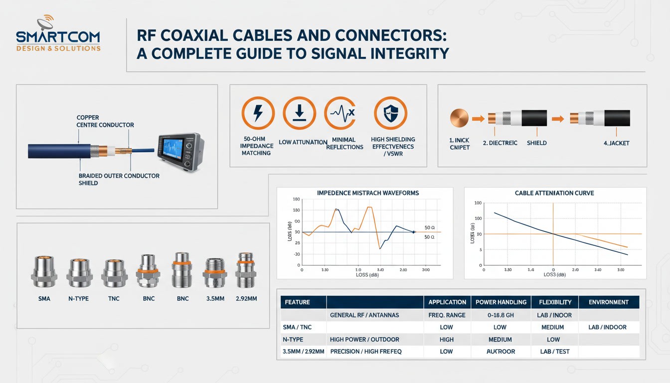
In RF and microwave systems, signal performance depends on more than antennas, amplifiers, filters, and other active components. The RF coaxial cables and connectors connecting these components also play an important role in maintaining signal quality throughout the signal path.
Incorrect impedance, excessive attenuation, poor connector interfaces, inadequate shielding, or unsuitable cable construction can introduce reflections, signal loss, interference, and other performance problems.
Understanding how RF coaxial cables, connectors, and cable assemblies work together helps engineers select suitable interconnect solutions for telecommunications, aerospace, defence, radar, satellite communication, wireless infrastructure, industrial systems, and RF test and measurement.
Key Takeaways
- RF cables and connectors are critical parts of the complete RF signal path.
- Maintaining consistent impedance helps minimise unwanted reflections.
- Cable attenuation and insertion loss should be evaluated across the required frequency range.
- Connector geometry and termination quality can influence VSWR and signal integrity.
- Shielding and cable construction should match the operating environment.
- Temperature, vibration, flexing, and PIM requirements should be considered for demanding applications.
- Testing the completed RF cable assembly helps verify electrical performance before deployment.
What Are RF Coaxial Cables and Connectors?
RF coaxial cables and connectors are interconnect components used to transmit radio-frequency signals between RF equipment while maintaining specified electrical characteristics.
An RF coaxial cable generally consists of a centre conductor, dielectric material, outer conductor or shield, and protective jacket. RF connectors provide the mechanical and electrical interface between the cable and equipment such as antennas, amplifiers, filters, RF modules, and test instruments.
Together, these components form an RF interconnect that must maintain the required impedance and electrical performance throughout the signal path.
An RF cable assembly combines a coaxial cable with connectors terminated at one or both ends. This provides a complete interconnection between RF components and can be configured according to application-specific electrical and mechanical requirements.
Why Signal Integrity Matters in RF Systems
At RF and microwave frequencies, a cable cannot be treated simply as a length of wire. It behaves as a transmission line with defined electrical characteristics.
RF signal integrity describes how effectively the required characteristics of a signal are maintained as it travels from the source to the load.
Several factors can affect signal integrity:
- Impedance mismatch
- Cable attenuation
- Insertion loss
- Connector discontinuities
- Poor shielding
- Signal reflections
- Passive intermodulation
- Temperature variation
- Mechanical movement
- Vibration and repeated flexing
When these factors are properly controlled, the interconnect introduces minimal unwanted effects into the RF system.
When they are not, the cable assembly can become a limiting factor in overall system performance.
Why 50-Ohm Impedance Is Important
50-ohm impedance is widely used in RF and microwave systems. Maintaining consistent characteristic impedance from the source to the load helps minimise signal reflections and provides predictable RF performance.
A typical RF signal path may contain:
RF source → cable → connector → adapter → cable → connector → RF load
Every transition in this path can introduce an impedance discontinuity. If the impedance changes significantly, part of the signal can be reflected toward the source.
This can increase VSWR, affect return loss, and reduce the amount of usable power delivered to the load.
For this reason, the cable, connector, adapter, and equipment interfaces should be selected to provide compatible impedance throughout the complete signal path.
Construction of an RF Coaxial Cable
An RF coaxial cable contains several layers that work together to control signal transmission while providing mechanical and environmental protection.
Centre Conductor
The centre conductor carries the RF signal.
Depending on the cable design and application, conductors may use copper or plated copper. At high frequencies, the skin effect causes RF current to concentrate near the conductor surface, making conductor construction an important consideration for signal loss.
Dielectric
The dielectric separates the centre conductor from the outer conductor.
Common dielectric materials include PTFE and polyethylene-based materials.
The dielectric influences:
- Characteristic impedance
- Propagation velocity
- Attenuation
- Flexibility
- Temperature performance
Different dielectric constructions can therefore be selected according to the electrical and mechanical requirements of the application.
Outer Conductor and Shield
The outer conductor provides the return path for the RF signal and contributes to electromagnetic shielding.
Depending on the cable design, it may consist of:
- Braid
- Foil
- Solid conductor
- Corrugated conductor
The outer conductor affects shielding effectiveness, signal leakage, mechanical strength, flexibility, and environmental performance.
Outer Jacket
The outer jacket protects the cable from mechanical and environmental conditions.
Depending on the application, the jacket may need to withstand:
- Moisture
- UV exposure
- Temperature variation
- Abrasion
- Repeated flexing
- Installation stress
The cable jacket should therefore be selected according to the expected operating environment.
Why RF Connectors Are Important
RF connectors create the mechanical and electrical interface between an RF cable and another component.
Unlike the uniform construction of a cable, a connector contains a mating interface where the transmission geometry changes. Connector design, manufacturing precision, contact quality, and termination therefore have a direct influence on RF performance.
Connector selection should consider:
- Frequency range
- Characteristic impedance
- VSWR
- Insertion loss
- Power handling
- Mechanical configuration
- Mating cycles
- Environmental requirements
- Equipment compatibility
Physical compatibility alone is not enough. The connector must also meet the electrical and mechanical requirements of the application.
Common RF Connector Types
Different connector interfaces are designed for different frequency ranges, mechanical requirements, and applications.
RF Connector | Coupling | Key Consideration | Common Applications |
SMA | Threaded | Compact RF/microwave interface | RF modules, test equipment, antennas |
N-Type | Threaded | Robust mechanical construction | Telecom, antennas, outdoor RF |
TNC | Threaded | Secure mechanical connection | Wireless and RF systems |
BNC | Bayonet | Quick-connect interface | Test equipment, instrumentation |
3.5 mm | Threaded | Precision microwave performance | High-frequency test systems |
2.92 mm | Threaded | Higher-frequency applications | Microwave systems |
7/16 DIN | Threaded | High-power RF applications | Telecom infrastructure |
The correct connector should be selected according to the required frequency range, impedance, power level, mechanical configuration, environmental conditions, and equipment interface.
How RF Connectors Affect Signal Integrity
Connector performance can influence the overall performance of an RF cable assembly in several ways.
Connector Geometry
The internal geometry of an RF connector must maintain controlled impedance through the mating interface.
Poor geometry or manufacturing variation can introduce reflections and affect VSWR.
Contact Quality
Reliable electrical contact is essential for consistent RF transmission.
Contamination, wear, oxidation, poor alignment, or damaged contact surfaces can affect performance and long-term reliability.
Plating
Connector plating can influence conductivity, corrosion resistance, durability, and long-term contact performance.
The appropriate material and finish depend on the connector design and application.
Mating and Torque
Threaded connectors require appropriate mating procedures and torque.
Incorrect installation can damage the interface or affect electrical performance.
This is particularly important in laboratory, calibration, test and measurement, and high-frequency applications where connectors may be repeatedly mated and unmated.
Common RF Signal Integrity Problems
Even a well-designed RF system can experience performance problems if the interconnect is incorrectly specified, terminated, installed, or maintained.
Impedance Mismatch
An impedance mismatch between a cable, connector, adapter, or equipment interface can cause signal reflections.
Common indicators include:
- Increased VSWR
- Reduced return loss
- Reflected power
- Reduced power transfer
Cable Attenuation
Attenuation represents the reduction in signal power as an RF signal travels through a cable.
Cable attenuation depends on factors such as:
- Operating frequency
- Cable length
- Conductor construction
- Dielectric material
- Cable design
Attenuation generally becomes more significant as frequency and cable length increase.
Insertion Loss
Insertion loss describes the reduction in signal power introduced by an interconnect or component in the signal path.
When specifying an RF cable assembly, evaluate insertion loss across the complete operating frequency range rather than relying only on a single frequency value.
Inadequate Shielding
Poor shielding can allow external electromagnetic energy to enter the signal path or allow RF energy to escape from the cable.
Shielding becomes particularly important in environments containing transmitters, switching equipment, motors, high-power RF equipment, or sensitive receivers.
Connector Interface Problems
Incorrect connector selection, damaged interfaces, poor termination, contamination, or incompatible connector configurations can create electrical discontinuities.
These problems can affect:
- VSWR
- Insertion loss
- Reliability
- Repeatability
- Signal integrity
Passive Intermodulation
Passive intermodulation (PIM) can create unwanted RF signals when nonlinear behaviour occurs in passive components or connections.
PIM is particularly important in cellular and wireless infrastructure where multiple high-power RF signals may share the same system.
Connector condition, contact quality, contamination, materials, and mechanical integrity can all influence PIM performance.
Thermal and Mechanical Stress
Temperature changes, vibration, repeated flexing, and mechanical movement can influence cable performance.
Applications in aerospace, defence, satellite systems, mobile equipment, and other demanding environments may therefore require cable assemblies designed for stable electrical performance and mechanical reliability.
How to Choose the Right RF Cable Assembly
Selecting the right RF cable assembly requires consideration of both electrical and mechanical requirements.
Frequency Range
Identify the minimum and maximum operating frequencies of the system.
The selected cable and connector combination should support the complete frequency range with suitable electrical performance.
Impedance
Confirm the required system impedance and maintain compatibility between the cable, connectors, adapters, and equipment.
For many RF applications, this means maintaining a 50-ohm interconnect throughout the signal path.
Attenuation and Insertion Loss
Evaluate cable attenuation and total insertion loss at the actual operating frequency.
This is particularly important for long cable assemblies and systems operating with low signal levels.
VSWR and Return Loss
VSWR and return loss help evaluate impedance matching and signal reflections.
For high-frequency applications, establish the required performance limits before specifying the cable assembly.
Power Handling
The assembly must be capable of handling the expected RF power under the intended operating conditions.
Power-handling requirements can depend on frequency, cable construction, connector design, ambient temperature, and installation conditions.
Connector Type
Select connectors based on:
- Equipment interface
- Frequency range
- Impedance
- Mechanical requirements
- Power requirements
- Environmental conditions
The connector must provide both mechanical compatibility and the required electrical performance.
Flexibility
Determine whether the cable will remain stationary or move repeatedly.
Flexible cables can be suitable for test setups and moving equipment, while semi-rigid constructions can be useful where controlled geometry and stability are important.
Environmental Conditions
Outdoor, aerospace, defence, telecom, and industrial systems may require cable assemblies that can withstand:
- Temperature variation
- Moisture
- Vibration
- UV exposure
- Mechanical stress
- Repeated flexing
The cable jacket, shielding, conductor construction, connector materials, and termination method should all be considered as part of the complete assembly specification.
RF Coaxial Cable vs RF Cable Assembly
An RF coaxial cable refers to the cable itself, including its conductor, dielectric, outer conductor, and jacket.
An RF cable assembly includes the cable together with connectors terminated at one or both ends.
Feature | RF Coaxial Cable | RF Cable Assembly |
Cable | Yes | Yes |
Connectors | No | Yes |
Termination | No | Yes |
Ready to install | Usually no | Yes |
Custom connector configuration | Limited | Yes |
Complete interconnection | No | Yes |
Application-specific configuration | Limited | Yes |
A cable may have excellent electrical characteristics, but the completed assembly can still perform poorly if the connectors are unsuitable or the termination is incorrect.
Therefore, evaluate the complete assembly rather than the cable in isolation.
RF Cable Assembly Selection Guide
Selection Factor | Why It Matters |
Frequency range | Determines whether the cable and connector can support the required frequencies |
Impedance | Helps minimise reflections and maintain system compatibility |
VSWR | Indicates the degree of impedance mismatch |
Insertion loss | Indicates signal loss introduced by the assembly |
Cable length | Influences total attenuation |
Power handling | Determines suitability for the required RF power |
Connector type | Ensures mechanical and electrical compatibility |
Flexibility | Determines suitability for stationary or moving applications |
Shielding | Helps protect against electromagnetic interference |
Environment | Determines required temperature, moisture, vibration, UV, and mechanical resistance |
Evaluating these factors together helps engineers select an RF cable assembly that matches the actual system requirements.
Applications of RF Cable Assemblies
RF cable assemblies are used wherever controlled transmission of RF and microwave signals is required.
Common applications include:
- Telecommunications infrastructure
- Wireless communication
- Defence electronics
- Aerospace systems
- Satellite communication
- Radar systems
- RF test and measurement
- Antenna systems
- Microwave equipment
- Industrial RF systems
Each application may require a different combination of frequency capability, insertion loss, VSWR, power handling, flexibility, shielding, and environmental durability.
How to Test an RF Cable Assembly?
Testing helps verify that an RF cable assembly meets the required electrical and mechanical specifications.
VSWR Testing
VSWR testing evaluates the degree of impedance mismatch within the RF signal path.
A higher-than-expected VSWR can indicate a problem with the cable, connector, termination, or equipment interface.
Insertion Loss Testing
Insertion loss testing measures the signal power lost through the cable assembly.
The measurement should be evaluated across the required frequency range.
Return Loss Testing
Return loss provides information about reflected signal power caused by impedance mismatch.
It is useful for assessing the quality of the RF transmission path and identifying potential discontinuities.
Power Testing
Where required, power-handling tests can help verify that the assembly performs reliably under the intended RF power conditions.
Environmental Testing
Depending on the application, cable assemblies may require environmental testing such as:
- Temperature cycling
- Vibration testing
- Mechanical testing
- Environmental exposure testing
Testing requirements should be established according to the application’s performance and reliability requirements.
How to Improve RF Signal Integrity
Several practical measures can help improve RF interconnect performance:
- Maintain the required characteristic impedance throughout the signal path.
- Select cables and connectors according to the operating frequency.
- Minimise unnecessary adapters and junctions.
- Select connectors that match the equipment interfaces.
- Follow the manufacturer’s recommended mating and torque procedures.
- Consider attenuation and insertion loss before finalising cable length.
- Select appropriate shielding for the installation environment.
- Consider PIM requirements for wireless and cellular applications.
- Account for temperature, vibration, and repeated flexing where applicable.
- Test the completed assembly before deployment.
A complete approach to cable selection, connector choice, termination, installation, and testing reduces the likelihood of unexpected RF performance issues
Why Custom RF Cable Assemblies Can Be Important
Not every RF system can use a standard off-the-shelf cable.
Custom RF cable assemblies can be specified according to requirements such as:
- Cable length
- Connector combination
- Connector orientation
- Frequency range
- Impedance
- Insertion loss
- VSWR
- Power handling
- Flexibility
- Environmental conditions
Customisation can support system integration when equipment layouts, mechanical clearances, connector interfaces, or electrical requirements are unique to the application.
Choose the Right RF Interconnect for Your Application
Need an RF cable assembly, coaxial cable, or RF connector for a specific application? Share your frequency range, impedance, connector type, cable length, power requirements, and operating environment with Smartcom India to discuss a suitable interconnect configuration.
Conclusion
RF coaxial cables and connectors are essential components of the RF signal path. Their electrical and mechanical characteristics directly influence signal integrity, attenuation, impedance matching, VSWR, shielding, and overall system reliability.
Selecting an RF interconnect requires evaluation of the complete RF cable assembly, including cable construction, connector interface, frequency range, impedance, insertion loss, power handling, mechanical requirements, and operating environment.
The right combination of cable, connector, termination, installation, and testing can help ensure reliable RF performance across demanding applications.
FAQ
Which RF cable or connector should I choose for my application?
The appropriate RF cable assembly and connector depend on operating frequency, impedance, insertion loss, VSWR, power handling, cable length, flexibility, environmental conditions, and equipment interface.
How can I troubleshoot RF signal integrity problems?
Start by checking the complete signal path for damaged cables, lose or contaminated connectors, incorrect impedance, excessive cable loss, and unnecessary adapters or junctions. Measurements such as VSWR, return loss, and insertion loss can help identify potential problems.
How should an RF cable assembly be tested?
An RF cable assembly can be evaluated using suitable RF test equipment, including a vector network analyzer (VNA), to measure parameters such as VSWR, return loss, and insertion loss across the required frequency range. Additional power or environmental testing may be necessary for specialised applications.
What are the best practices for RF connector installation?
Use the correct connector for the application, keep mating surfaces clean, avoid damaging the connector interface, follow the manufacturer's recommended mating procedure and torque specifications, and prevent excessive bending or mechanical stress near the termination.
How should RF cable assemblies be specified for harsh environments?
For applications involving high vibration, temperature variation, moisture, UV exposure, or mechanical stress, specify the complete assembly according to the environmental requirements. Consider the cable jacket, shielding, conductor construction, connector materials, termination method, and mechanical stability.
When should I consider a custom RF cable assembly?
A custom RF cable assembly can be useful when standard assemblies do not meet requirements for cable length, connector combination, connector orientation, frequency range, VSWR, insertion loss, power handling, flexibility, or environmental performance.