
What Is an RF Triplexer? Working Principle, Design and Applications
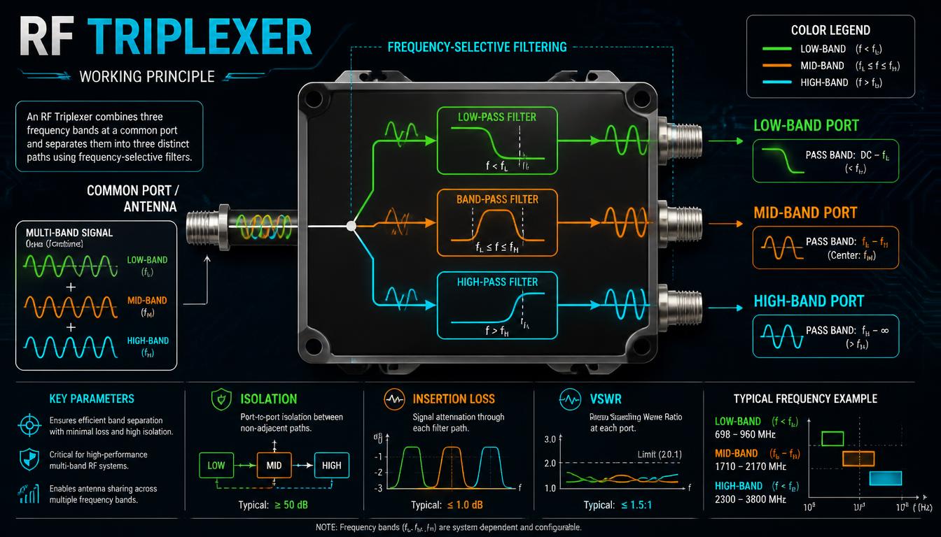 RF Triplexer Working Principle Diagram
RF systems sometimes need to manage three different frequency bands through a shared antenna or transmission path. A component designed for this purpose can help reduce the need for separate signal paths for each band. An RF triplexer uses frequency-selective branches to combine or separate three frequency bands.
Understanding the RF triplexer working principle helps engineers evaluate its suitability for multi-band wireless equipment, communication systems and other RF applications. Its performance depends on the frequency plan, branch isolation, insertion loss, power handling, and impedance matching.
Looking for Custom RF Triplexers?
Speak directly with our RF component specialists to discuss your specifications.
What Is an RF Triplexer?
An RF triplexer is a frequency-selective RF component that combines three frequency bands onto a common port or separates signals from a common port into three band-specific paths.
A typical triplexer has one common port and three frequency-selective ports. Each branch passes a defined frequency range while attenuating frequencies outside its intended passband.
A triplexer is used when three operating bands must share an antenna feed or another common RF connection. The component must be designed for the actual frequency bands and power levels involved.
How Does an RF Triplexer Work?
An RF triplexer works on three frequency-selective paths connected to a common port.
Each branch is designed for a different frequency band. During reception, the filtering network routes signals arriving at the common port to the relevant branches based on the frequency response. During transmission, the triplexer can combine signals from the three branch ports onto the common port when it is designed and rated for that operation.
The branches must be designed to manage their passbands and unwanted signals. Their interaction affects isolation, insertion loss, matching, and overall system performance.
Understanding the Four-Port Configuration
Common Port
The common port connects the triplexer to a shared antenna, transmission line or other RF interface.
Three Frequency-Band Ports
Each branch serves a different operating band. The frequency ranges must match the system’s operating plan.
Frequency-Selective Networks
The internal filtering network defines each branch’s response. Depending on the design, it may use cavity resonators or another suitable RF filtering topology.
RF Triplexer vs RF Diplexer
A diplexer manages two frequency bands, while a triplexer manages three. Both use frequency-selective paths connected to a common port.
The choice depends on how many frequency bands need to share a path. A triplexer is not automatically better than a diplexer: it is appropriate when the system requires three bands and its electrical specifications meet the application requirements.
For a more detailed component comparison, refer to the dedicated RF cavity filters, diplexers and triplexers product page.
Important RF Triplexer Specifications
Frequency Bands and Bandwidth
Each of the three branches must support its intended frequency range. Engineers should check the passband limits and any required transition or guard bands.
Insertion Loss
Insertion loss indicates how much signal power is lost along a relevant path. The acceptable value depends on the system’s link budget and application.
Port-to-Port Isolation
Isolation indicates how effectively the device controls unwanted signal transfer between paths. Adequate isolation matters when multiple frequency bands share the same assembly.
VSWR and Return Loss
These parameters help evaluate impedance matching at the ports. Reflections can affect the overall RF chain performance.
Power Handling
The triplexer must support the relevant transmit power and operating conditions. Thermal limits and peak-power requirements should also be checked when applicable.
Size and Connector Requirements
The mechanical envelope, mounting arrangement and connector interfaces must suit the equipment in which the triplexer will be installed.
Where Are RF Triplexers Used?
RF triplexer applications may include:
- Multi-band communication equipment
- Shared-antenna RF systems
- Telecom infrastructure supporting multiple frequency bands
- Selected satellite and microwave communication systems
- Radio equipment with three distinct frequency paths
- RF test arrangements requiring three frequency-selective branches
The correct use case depends on the operating frequencies, system architecture and verified component specifications.
How to Choose an RF Triplexer
Before selecting a triplexer, document the following:
- All three required frequency bands.
- The bandwidth and rejection requirements for each branch.
- Acceptable insertion loss for each signal path.
- Required isolation between branches.
- VSWR and return-loss limits.
- Continuous and peak RF power requirements.
- Impedance and connector types.
- Environmental conditions, mounting and available space.
These details help engineers determine whether an available configuration meets the system requirements or whether a custom design is needed.
Explore RF Triplexer Options with Smartcom India
Smartcom India lists RF triplexers alongside diplexers and cavity filters. Its product page lists published passband and performance details for each configuration.
Visit the RF cavity filters, diplexers and triplexers page to review the available information and enquire about your frequency requirements.
For a useful technical discussion, provide the three operating bands, required isolation, insertion loss, power rating, connector type and mechanical constraints.
Explore RF Diplexers and Triplexers
Conclusion
An RF triplexer enables three frequency bands to share a common RF path through frequency-selective branches. Its suitability depends on the system’s frequency plan and the component’s electrical and mechanical performance.
Engineers should review each branch’s specifications and verify compatibility with the complete RF system before selecting a triplexer.
FAQ
What does an RF triplexer do?
An RF triplexer combines or separates three frequency bands using frequency-selective branches connected to a common port.
How many ports does a triplexer have?
A typical triplexer has four ports: one common port and three frequency-band ports.
What is the difference between an RF diplexer and an RF triplexer?
A diplexer manages two frequency bands, while a triplexer manages three. The right component depends on the number of bands and the system's electrical requirements.
Can a triplexer connect three frequency bands to one antenna?
It can be used for that purpose when the triplexer, antenna and overall RF system are designed for the required frequency bands and power levels.
Which specifications are important when selecting an RF triplexer?
Check frequency range, bandwidth, insertion loss, isolation, VSWR, return loss, power handling and connector compatibility for all relevant paths.