
How to Choose the Right RF Attenuator for Your Application?
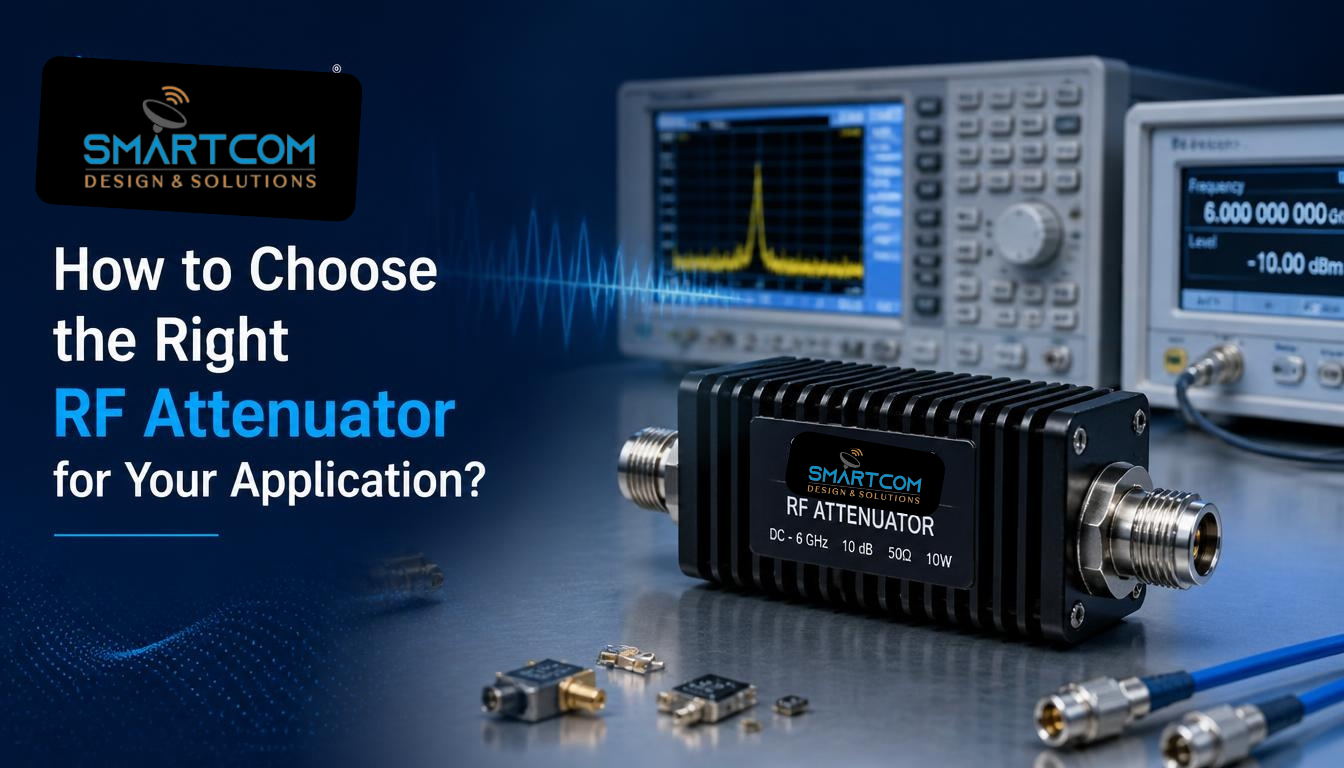
Selecting the right RF attenuator is important for controlling signal levels, reducing the risk of receiver overload, and maintaining predictable performance in RF and microwave systems. An attenuator reduces the power of an RF signal by a specified amount, measured in decibels (dB). It is commonly used in RF testing, communication systems, receiver circuits, and other applications that require controlled signal levels.
However, choosing an RF attenuator involves more than selecting an attenuation value. Engineers must consider the operating frequency, input power, impedance, attenuation accuracy, Voltage Standing Wave Ratio (VSWR), and connector type before selecting a suitable component.
Smartcom offers fixed and digital step RF attenuators for different frequency and power requirements.
Need a Custom RF Attenuator for Your Application?
If your system requires a specific frequency combination, attenuation range, power rating, or connector configuration, discuss your technical requirements with Smartcom.
Understand Your Required Attenuation Value
The first step is to identify how much signal reduction your RF system requires. Attenuation is measured in decibels (dB), which represents the reduction in signal power between the input and output.
For example, a 10 dB attenuator reduces the input signal power to one-tenth of its original value.
The output power can be calculated using the following formula:
Output Power = Input Power × 10^(-Attenuation / 10)
Consider an RF signal with an input power of 10 watts passing through a 6 dB attenuator.
- Input power: 10 W
- Attenuation: 6 dB
- Output power: Approximately 2.51 W
This means the signal power is reduced from 10 W to approximately 2.51 W.
Selecting the correct attenuation value helps maintain the required signal level without introducing unnecessary signal loss.
Choose Between Fixed and Digital Step RF Attenuators
RF attenuators are available in different types depending on how the attenuation level needs to be controlled.
Fixed RF Attenuators
A fixed RF attenuator provides a specific attenuation value that cannot be changed during operation. It is suitable for applications where the required signal reduction remains constant.
Common applications include:
- RF test and measurement equipment
- Signal conditioning circuits
- Communication systems
- Transmitter and receiver circuits
Digital Step RF Attenuators
A digital step attenuator provides multiple attenuation levels that can be selected electronically. It is useful when signal levels need to be adjusted during system operation.
Common applications include:
- Automated RF testing
- Wireless communication systems
- Signal level control
- RF research and development
When selecting a digital step attenuator, consider the available attenuation steps, control interface, switching speed, and repeatability.
The choice between fixed and digital step attenuators depends on whether your application requires constant attenuation or adjustable signal control.
Looking for an RF attenuator for your next project? Explore the Smartcom RF Attenuator product range.
Check the Operating Frequency Range
Frequency range is one of the most important specifications when selecting an RF attenuator.
Every attenuator is designed to operate within a specified frequency range. Using a component outside its specified range can affect attenuation accuracy, impedance matching, and overall RF performance.
For example:
- DC to 3 GHz may be suitable for applications operating within that frequency range.
- DC to 6 GHz supports systems requiring wider frequency coverage.
- DC to 18 GHz is relevant for applications operating across a wider RF and microwave frequency range.
Before selecting an RF attenuator, identify the minimum and maximum operating frequencies of your system.
Also check whether the attenuation remains within the required tolerance across the complete operating frequency range.
Verify the RF Power Handling Capacity
Power handling determines how much RF input power an attenuator can safely handle under its specified operating conditions.
This is particularly important in high-power RF systems, where the component must dissipate the power removed from the signal.
For example, a 50 W RF attenuator and a 500 W RF attenuator are designed for different input power requirements.
When selecting an attenuator, consider:
- Maximum continuous wave (CW) power.
- Peak power requirements for pulsed signals.
- Operating temperature.
- Cooling and heat dissipation.
- Duty cycle and installation conditions.
Continuous wave power and peak power should not be treated as interchangeable ratings. A component suitable for a particular average power may not support the same power level under every pulsed operating condition.
Also, check the manufacturer’s power derating guidelines because the allowable input power may vary with operating frequency, ambient temperature, and cooling conditions.
Always check the manufacturer’s specified operating limits before using an attenuator in a high-power system.
Understand Attenuation Accuracy and Tolerance
Attenuation accuracy indicates how closely the actual signal reduction matches the specified attenuation value.
For example, consider a hypothetical 10 dB attenuator with a tolerance of ±0.5 dB. Its actual attenuation may range from 9.5 dB to 10.5 dB under the specified test conditions.
Accuracy matters in applications where signal levels must stay within defined limits.
When comparing RF attenuators, check:
- Maximum attenuation tolerance.
- Attenuation variation across frequency.
- Stability under operating temperature conditions.
- Repeatability of attenuation settings for digital models.
For precision testing and measurement applications, consider attenuation accuracy carefully.
Check VSWR and Impedance Matching
Voltage Standing Wave Ratio (VSWR) indicates how well an RF component matches the impedance of the connected transmission system.
An impedance mismatch can cause part of the RF signal to reflect towards the source instead of being transferred to the load.
Most RF attenuator applications use a 50-ohm impedance system. Therefore, the attenuator should match the impedance requirements of the connected RF equipment.
A lower VSWR generally indicates a better impedance match.
For example, a component with a maximum VSWR of 1.2:1 has a better specified match than one with a maximum VSWR of 1.5:1.
When selecting an attenuator, check the VSWR specification across the required frequency range rather than considering only one frequency point.
In systems that require forward and reflected power monitoring, RF directional couplers can also sample signals to support power measurement and VSWR monitoring.
Select the Correct RF Connector Type
The connector type affects how the attenuator connects to the rest of the RF system.
Common RF connector options include:
- SMA connectors
- N-type connectors
- 7/16 DIN connectors
The correct connector depends on the operating frequency, power requirements, mechanical arrangement, and the equipment’s connector interface.
Before ordering an RF attenuator, verify the connector gender, interface, and compatibility with the existing RF cables and equipment.
You can also explore Smartcom’s RF Connectors to understand the available connector options for RF and microwave systems.
For complete interconnection requirements, consider the cable type, connector configuration, and operating frequency together. Smartcom also provides RF Coaxial Cable Assemblies for different RF applications.
Consider the Application Before Selecting the Model
Different RF applications have different attenuation and power requirements. Understanding the operating environment helps engineers identify the specifications that matter most.
Application | Important selection factors |
RF testing and measurement | Attenuation accuracy, frequency range, VSWR |
Wireless communication | Frequency coverage, signal control, impedance |
Defence and radar systems | Power handling, frequency range, environmental requirements |
Satellite communication | Microwave frequency coverage, accuracy, impedance matching |
High-power RF systems | CW power rating, thermal management, connector compatibility |
The required specifications should always be based on the system’s actual operating conditions.
Compare RF Attenuator Specifications Before Making a Decision
Before finalising an RF attenuator, compare the specifications provided in the manufacturer’s product datasheet.
The following table highlights selected RF attenuator models.
Model | Frequency Range | Attenuation | Maximum Tolerance | Maximum VSWR | Maximum CW Power |
SATT-XY-10-DC3G | DC–3 GHz | 1–19 / 20–60 dB | ±0.5 / ±0.8 dB | 1.3 | 10 W |
SATT-XY-10-DC6G | DC–6 GHz | 1–30 dB | ±1.5 dB | 1.3 | 10 W |
SATT-XY-50-DC3G | DC–3 GHz | 1–19 / 20–40 dB | ±0.6 / ±1.0 dB | 1.2 | 50 W |
SATT-XY-50-DC18G | DC–18 GHz | 3–40 dB | ±1.5 dB | 1.35 | 50 W |
SATT-XY-100-DC18G | DC–18 GHz | 6–60 dB | ±1.5 dB | 1.4 | 100 W |
SATT-XY-200-DC18G | DC–18 GHz | 10–60 dB | ±1.4 dB | 1.45 | 200 W |
SATT-XY-500-DC18G | DC–18 GHz | 10–60 dB | ±1.5 dB | 1.5 | 500 W |
SATT-XY-1000-DC3G | DC–3 GHz | 10–60 dB | ±2.5 dB | 1.3 | 1,000 W |
When Should You Consider a Custom RF Attenuator?
Standard RF attenuators may not meet every system requirement. Custom designs may be required when an application needs a particular combination of:
- Operating frequency.
- Attenuation range.
- Power handling capacity.
- Impedance requirements.
- Connector configuration.
- Mechanical dimensions.
For specialised RF and microwave systems, discussing these requirements with the manufacturer can help identify a suitable design.
Explore Smartcom’s RF Attenuator Range
Looking for an RF attenuator for your specific frequency and power requirements?
Explore Smartcom’s range of fixed and digital-step RF attenuators, with power-handling options up to 1,000 W CW and frequency coverage up to 18 GHz.
- Compare available attenuation ranges.
- Check power handling and VSWR specifications.
- Review frequency and connector requirements.
Explore RF Attenuator Models and Specifications
Need help identifying a suitable model? Share your operating frequency, required attenuation, and input power with Smartcom’s engineering team to discuss your application requirements.
Conclusion
Choosing the right RF attenuator requires careful consideration of attenuation value, frequency range, power handling, accuracy, VSWR, and connector compatibility.
A suitable component should meet the electrical and operating requirements of the complete RF system, not just one specification.
Whether your application requires a fixed RF attenuator, a digital step attenuator, or a high-power solution, comparing technical specifications before selection can help achieve reliable signal control and consistent system performance.