
What Is an RF Coupler? Types, Working and Applications
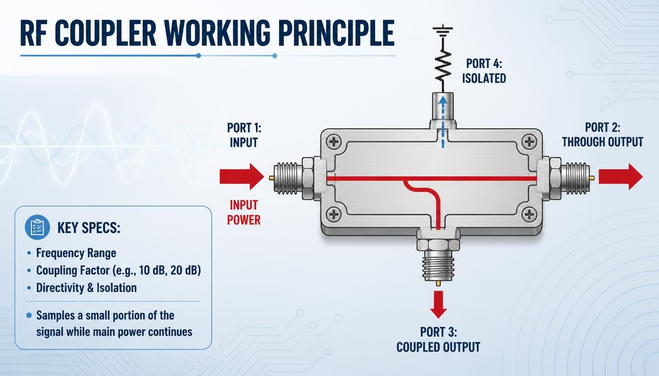
How Does an RF Coupler Work?
An RF coupler transfers a controlled portion of electromagnetic energy from the main signal path to another port. Depending on the design, this coupling takes place through electromagnetic fields between transmission lines or through transformer-based structures.
The amount of power transferred is described by the coupling factor, expressed in decibels (dB).
For example:
- A 10 dB coupling factor means approximately 10% of the input power appears at the coupled port.
- A 20 dB coupling factor means approximately 1% of the input power appears at the coupled port.
- A 30 dB coupling factor means approximately 0.1% of the input power appears at the coupled port.
The remaining power continues along the main transmission path, subject to insertion loss. Actual performance depends on the component’s design and operating conditions.
Main Types of RF Couplers
Directional couplers (unidirectional):
Sample power travelling in one direction. They are typically used to monitor forward power in RF systems.Dual directional couplers:
Provide separate coupled outputs for monitoring forward and reflected power. This allows both signal directions to be evaluated within an RF system.Hybrid couplers:
Divide an input signal between two output ports with a defined phase relationship. A 3 dB hybrid coupler ideally divides the input power equally between the two outputs.
Naming and port configurations can vary between manufacturers. Always check the manufacturer’s datasheet when comparing different coupler configurations.
Key Specifications to Compare
When evaluating RF couplers, consider the following specifications:
- Frequency range
- Coupling factor
- Directivity
- Insertion loss
- VSWR
- Isolation
- Power handling
- Temperature range
These specifications help determine whether a coupler is suitable for the frequency, power, and measurement requirements of an RF system. For hybrid couplers, amplitude balance and phase balance may also be important.
Where RF Couplers Are Used
RF couplers are used in applications that require signal monitoring, power measurement and signal distribution.
Typical applications include transmitter output power monitoring, forward and reflected power measurement, VSWR protection circuits, feedback and levelling circuits, and RF test and measurement equipment.
Smartcom’s RF directional couplers are intended for applications including military and defence communication systems, telecom base stations and RF infrastructure, aerospace and satellite platforms, RF test and measurement equipment, and power monitoring circuits.
The coupled output may also be connected to a power meter through an RF attenuator when the sampled signal needs to be reduced to a level suitable for the measuring instrument.
RF Coupler or Power Divider?
An RF coupler and a power divider are both used in RF signal distribution, but they serve different purposes.
A directional coupler samples a small, controlled portion of the signal while allowing most of the power to continue along the main path. A power divider splits the input signal between two or more output paths, typically with a defined power distribution.
If you need to monitor RF power, a directional coupler is generally suitable. If you need to distribute a signal across multiple paths, explore RF power dividers and combiners.
For a detailed comparison, read our article on Directional Coupler vs Power Divider.
How to Choose an RF Coupler by an Expert
Selecting an RF coupler depends on your system’s operating requirements.
- Match the frequency range to your system’s operating frequency.
- Select a coupling factor that provides the required signal level for your measuring instrument or circuit.
- Choose directivity based on how accurately your system needs to distinguish forward and reflected power. Read more about directional coupler directivity.
- Check that the power handling capability covers your system’s operating and peak transmit power.
- Review VSWR, insertion loss and other relevant specifications to ensure compatibility with your RF system.
Why Choose Smartcom India for RF Couplers?
Choosing an RF coupler involves evaluating frequency coverage, coupling factor and power-handling requirements. Smartcom India offers RF directional couplers with frequency coverage from 100 MHz to 18 GHz and coupling factor options ranging from 3 dB to 50 dB.
These product options support different requirements across telecommunications, military and defence communication, aerospace, satellite systems, and RF test and measurement applications.
Whether you are specifying a coupler for signal monitoring or integrating it into an RF communication system.
Contact our team to discuss your RF component specifications.