
Making RF Assembly Manufacturing More Efficient: Key Considerations Before Production
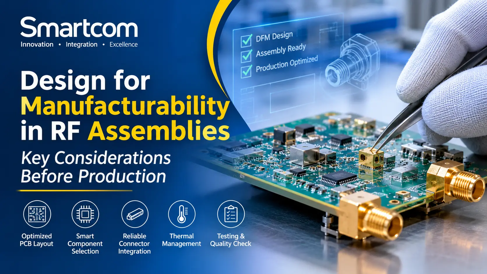
Designing an RF assembly requires attention to electrical performance and manufacturing requirements. The design must support PCB fabrication, component assembly, inspection, and testing.
A circuit that works well in a prototype may present challenges during production. Component availability, PCB layout, connector placement and assembly tolerances can affect the manufacturing process.
Design for Manufacturability (DFM) helps engineers identify these issues before production begins. Considering manufacturing requirements during the design stage can reduce avoidable rework and simplify production planning.
This guide covers the main DFM considerations for RF assemblies. For related manufacturing and integration capabilities, visit Smartcom’s Systems Integration and Assembly Works.
Discover how Smartcom can support your assembly and integration needs.
What Is Design for Manufacturability?
Design for Manufacturability is the process of designing a product so it can be manufactured and assembled using suitable production methods.
In RF assemblies, DFM considers electrical performance, PCB layout, component selection, mechanical design and assembly requirements.
The aim is to ensure that the design meets its technical specifications while remaining practical to manufacture, inspect and test.
Why Is DFM Important in RF Assemblies?
RF assemblies contain components that require careful placement, suitable connections and proper mechanical integration.
Changes in component placement, signal routing or grounding can affect RF performance. Designs that are difficult to assemble may also increase production time and rework.
Applying DFM principles early helps engineers:
- Identify manufacturing issues before production.
- Reduce avoidable assembly errors.
- Review component availability.
- Improve assembly and inspection access.
- Plan testing requirements.
- Prepare designs for repeatable production.
These checks are particularly important when moving from prototype development to production.
Review the RF Circuit and PCB Layout
PCB layout affects both RF performance and manufacturing requirements.
RF circuits may require controlled-impedance transmission lines, suitable grounding structures and careful component placement.
During the design review, consider:
- Controlled impedance for RF signal paths.
- PCB trace widths and stack-up specifications.
- Grounding and return-current paths.
- Component spacing and assembly access.
- Separation of sensitive RF paths from interference sources.
- Signal integrity and electromagnetic compatibility (EMC).
- PCB fabrication capabilities and tolerances.
The layout should match the selected PCB manufacturer’s capabilities.
For example, designs requiring fine features or specialised PCB materials may need additional fabrication checks.
Where filtering is part of the circuit design, engineers should also review the required RF filters and their electrical specifications.
Select Components for Performance and Availability
Component selection affects RF performance and production planning.
A component may meet the electrical requirements but have limited availability or may not suit the intended assembly process.
Consider the following factors:
- Electrical specifications: Check whether the component meets the required RF performance.
- Package and footprint: Confirm compatibility with the PCB layout.
- Availability: Review sourcing options and lead times.
- Lifecycle status: Check whether the component is still available.
- Alternative components: Evaluate possible replacements before approving substitutions.
Check component alternatives for electrical and mechanical compatibility.
In RF assemblies, footprint and parasitic differences can affect circuit performance. Any replacement should undergo appropriate engineering review.
Plan RF Connector Integration
RF connectors connect an assembly to external cables, antennas and other equipment.
Their placement affects signal connections, mechanical fit and accessibility during assembly.
Consider these points during design:
- Connector type and operating frequency range.
- Required impedance, such as 50 ohms or 75 ohms.
- Mounting and retention requirements.
- Cable connection and disconnection access.
- PCB footprint and soldering requirements.
- Clearance from nearby components and enclosure walls.
The connector must meet the assembly’s electrical and mechanical requirements.
For example, a connector placed too close to an enclosure wall may restrict cable access.
Explore Smartcom’s RF connectors, including its SMP(GPO) surface-mount PCB connector.
Consider Thermal Management
RF assemblies can generate heat through power dissipation in amplifiers and other electronic components.
Review thermal requirements during the design stage.
Important factors include:
- Power dissipation of individual components.
- Specified operating temperature ranges.
- PCB copper area and thermal paths.
- Heat sinks or cooling arrangements, where required.
- Enclosure design and ventilation.
- Access for temperature measurement during testing.
A component that operates within its specified temperature range during prototype testing may need further evaluation if the final enclosure or installation conditions are different.
Design for Assembly and Inspection
The assembly should be practical to manufacture using the intended production process.
Restricted component access, difficult soldering and complicated rework can increase manufacturing effort.
To improve assembly access:
- Provide suitable spacing between components.
- Avoid unnecessary mechanical obstructions.
- Follow the requirements of the selected PCB assembly process.
- Keep critical connections accessible for inspection.
- Include suitable mounting and alignment features.
- Identify components that require special handling.
Consider inspection requirements before production.
Critical connectors and high-density components may require specific inspection methods to check assembly quality.
Plan RF Assembly Testing Before Production
Define testing requirements during the design stage.
The required tests depend on the assembly’s application and technical specifications.
Common testing methods include:
- Visual inspection: Checks visible assembly defects.
- Continuity testing: Checks electrical connections.
- RF performance testing: Measures relevant RF characteristics against design specifications.
- Functional testing: Checks whether the assembly performs its intended function.
- Environmental testing: Evaluates performance under specified conditions, where required.
The test plan should identify the required equipment, measurement points, test conditions and acceptance criteria.
Planning RF production testing early helps ensure that the assembly can be inspected and tested using suitable procedures.
Prepare the Design for Production
A clear production handover helps manufacturing teams work with the approved design information.
Incomplete documentation can lead to assembly errors, component selection issues and production delays.
The production package should include:
- Approved schematic and PCB design files.
- Bill of Materials (BOM).
- PCB fabrication and assembly drawings.
- Mechanical drawings and enclosure requirements.
- Assembly instructions.
- Special handling requirements.
- Test procedures and acceptance criteria.
- Approved component alternatives, where applicable.
All documents should reflect the latest approved design.
Common DFM Challenges in RF Assemblies
The following issues may affect RF manufacturing and assembly:
Challenge | What to check |
Difficult component access | Review component spacing and assembly sequence. |
Component availability | Check sourcing options and lifecycle status. |
Connector placement | Review mounting and cable access. |
Thermal issues | Evaluate power dissipation and cooling requirements. |
Incomplete documentation | Prepare approved production files and instructions. |
Limited test access | Plan measurement points and test procedures. |
Reviewing these areas before production helps identify potential manufacturing issues early.
How Smartcom Supports RF Assembly and Integration
Smartcom provides RF and microwave solutions for communication and other technical applications.
Its Systems Integration and Assembly Works page lists capabilities including SMT and through-hole PCB assembly, RF and high-speed PCB assembly rework and modifications, functional testing, system-level integration, rapid prototyping and pilot production.
The company also lists environmental and reliability testing, including thermal cycling, vibration and power stress testing.
These capabilities cover different stages of RF product development, depending on project requirements.
Need expert assembly and integration support? Get in touch with our team!
Conclusion
Design for Manufacturability is an important part of preparing RF assemblies for production.
Reviewing PCB layout, component selection, connector integration, thermal management, assembly access and testing requirements helps engineers identify potential manufacturing issues before production begins.
A well-reviewed design makes the transition from prototype to production more organised and supports consistent manufacturing requirements.