
LNA vs RF Power Amplifier: Key Differences and Selection Criteria
Radio frequency (RF) systems use amplifiers to strengthen signals during transmission and reception. Two key types are low-noise amplifiers (LNAs) and RF power amplifiers (PAs). Although both increase signal strength, they serve different purposes within an RF communication system.
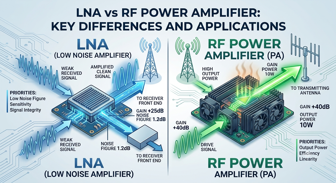
An LNA amplifies weak incoming signals while adding as little noise as possible. An RF power amplifier increases an RF signal’s power so it can drive a transmitting antenna or another load.
Understanding the difference between an LNA and an RF power amplifier helps engineers, equipment manufacturers and system integrators select suitable components for their applications. The right choice depends on factors such as operating frequency, gain, noise figure, output power, linearity and thermal requirements.
Smartcom India offers RF amplifier solutions, including low-noise amplifiers, driver amplifiers, broadband gain blocks, and RF power amplifiers for different applications.
Explore RF Amplifiers from Smartcom India.
1. What Is a Low Noise Amplifier (LNA)?
A low-noise amplifier is an RF component designed to amplify weak incoming signals while adding as little noise as possible. It is commonly used near a receiver input, where the signal may be too weak for reliable processing without amplification.
The first amplification stage is particularly important because noise added here can affect the receiver’s ability to detect the desired signal. An LNA is therefore designed with particular attention to noise figure, gain, impedance matching and stability.
How Does an LNA Work?
An LNA receives a low-level RF signal and increases its amplitude while limiting the additional noise introduced by the amplification process. Its performance depends on the device design and operating conditions.
For example, a wireless receiver may collect a weak signal from an antenna. An LNA amplifies that signal before it passes through further stages, such as filtering, frequency conversion and signal processing.
A suitable LNA can help preserve receiver sensitivity, but selecting one requires more than checking its noise figure alone. Engineers should also evaluate gain, linearity, frequency coverage, input power limits and stability.
LNAs are used in wireless communication receivers, satellite communication equipment, radar receiver front ends and other systems where weak-signal reception matters.
2. What Is an RF Power Amplifier?
An RF power amplifier increases an RF signal’s power so it can drive a load, such as a transmitting antenna. It is generally used in the transmitter section of a communication system.
Unlike an LNA, which prioritises low added noise, a power amplifier is selected mainly for its output power, gain, efficiency, linearity and ability to operate within specified thermal limits.
The required output power depends on the application. Some systems need modest amplification, while others require higher-power output stages.
RF power amplifiers are used in radio communication equipment, wireless transmitters, radar systems and specialised RF equipment. The appropriate model depends on the operating frequency, required output level, signal characteristics and system design.
3. LNA vs RF Power Amplifier: Key Differences
The main difference between an LNA and a power amplifier is their roles in the RF signal chain.
Comparison Factor | Low Noise Amplifier (LNA) | RF Power Amplifier (PA) |
Primary purpose | Amplifies weak received signals | Increases RF output power |
Typical position | Receiver front end | Transmitter output stage |
Main design priority | Low noise figure and adequate gain | Output power, efficiency and linearity |
Important specifications | Noise figure, gain, input limits and stability | Output power, gain, compression and thermal performance |
Main challenge | Preserving weak-signal quality | Delivering required power without excessive distortion or heat |
Typical application | Signal reception | Signal transmission |
Both amplifiers provide gain, but their design objectives differ. An LNA helps a receiver process weak signals, while a power amplifier helps a transmitter deliver sufficient RF power to its load.
Neither type should be selected based on a single specification. The component must meet the requirements of the complete system.
4. Important RF Amplifier Specifications to Understand
Before selecting an amplifier, review the datasheet and compare its specifications with the intended application.
Gain: Gain describes how much an amplifier increases signal level and is commonly expressed in decibels (dB). An LNA needs sufficient gain to support receiver performance. A power amplifier needs appropriate gain to achieve the required output level from the available input signal.
Noise figure: Noise figure measures how much noise an amplifier adds relative to an ideal noiseless amplifier. It is especially important in receiver applications involving weak signals. A lower noise figure is generally desirable for an LNA, provided it meets other system requirements.
Output power: The RF power the amplifier delivers. For a power amplifier, confirm that the specified output level suits the application and the conditions under which the device will operate.
Compression point: The 1 dB compression point (P1dB) indicates the point at which an amplifier’s gain has fallen by approximately 1 dB from its small-signal value. This helps engineers assess how close the amplifier is to compression and whether it needs additional operating margin.
Linearity and OIP3: Linearity describes how accurately an amplifier reproduces the input signal without introducing unacceptable distortion. Output third-order intercept point (OIP3) is one parameter used to assess certain nonlinear distortion effects. It is useful for comparisons but is not the same as the maximum usable output power.
Frequency range: The amplifier must cover the frequencies required by the system. Gain, noise figure, output power and impedance matching can vary across the operating band, so check performance across the complete frequency range.
Impedance and stability: Input and output matching affect how effectively signals transfer between connected components. Engineers should also check stability under the intended source, load and operating conditions.
Thermal performance: Power amplifiers can generate substantial heat depending on their operating conditions. Consider supply requirements, cooling, mounting, and duty cycle during system design.
Smartcom India’s RF amplifier product range provides information to help you evaluate amplifier options. Always verify the relevant specifications for the exact model before selecting one.
5. How to Choose Between an LNA and an RF Power Amplifier
The right amplifier depends on the circuit’s purpose. Use the following checks to narrow down your options.
Identify the signal-chain position. If the component must amplify a weak incoming signal, an LNA may be suitable. If it must deliver higher RF power to an antenna or load, a power amplifier is generally the relevant choice.
Define the frequency requirements. Confirm the operating frequency and bandwidth. The amplifier must cover the intended range while meeting the required performance across that band.
Determine the required gain. Estimate the expected input signal level and the required output level. Check that the amplifier can provide the necessary gain without exceeding its useful operating range.
Evaluate noise and linearity. For receiver front ends, noise figure is a key consideration. For transmitters, output power, efficiency and linearity may carry greater weight. Both amplifier types still need to meet the application’s stability and performance requirements.
Check power and thermal limits. Confirm supply voltage, current, input limits and output requirements. For power amplifiers, also consider cooling, duty cycle and heat dissipation.
Review the surrounding RF components. Filters, attenuators, connectors and cables affect the overall signal path. Consider Smartcom India’s RF filters when frequency selection or unwanted-signal rejection is required. Its RF attenuators are relevant where controlled signal reduction is needed.
The best amplifier is the one that meets the system’s actual requirements, not simply the one with the highest gain or output power.
6. Can an RF System Use Both an LNA and a Power Amplifier?
Yes. Many communication systems use both amplifier types because they perform different functions.
In a typical receiver path, an antenna receives an RF signal and passes it into the receiver chain. An LNA may amplify the weak signal early in that path, helping subsequent stages process it.
In a transmitter path, the system generates or processes an RF signal before sending it to a power amplifier. The amplifier increases the signal’s power to the level required by the connected load.
The complete system may also include filters, directional couplers, cables and connectors. For example, RF directional couplers can be used for signal sampling and power monitoring, depending on the design.
Using both amplifier types does not mean they are interchangeable. Select each based on its position, signal levels, and performance requirements.
7. Common Mistakes to Avoid When Selecting RF Amplifiers
Choosing an amplifier without checking the full set of requirements can lead to performance issues or unnecessary redesign.
- Selecting by gain alone: High gain does not guarantee low noise, sufficient output power or acceptable linearity.
- Ignoring frequency coverage: Confirm that the amplifier supports the required operating band.
- Overlooking compression: Operating too close to compression can create distortion and reduce signal quality.
- Neglecting thermal requirements: Power amplifiers may need suitable cooling and heat dissipation.
- Ignoring impedance matching: Poor matching can affect signal transfer and overall performance.
- Assuming all models are interchangeable: Amplifiers with similar headline specifications may differ in noise figure, power limits, stability and other important parameters.
- Failing to check system compatibility: Verify the amplifier alongside the connected filters, cables, connectors and other RF components.
Reviewing the datasheet and clearly understanding the intended application can help reduce these risks.
Why Choose Smartcom India?
Smartcom India designs and manufactures RF components, including low-noise amplifiers, driver amplifiers, broadband gain blocks, and RF power amplifiers. Its RF amplifier portfolio supports applications across sectors such as telecommunications, defence and aerospace.
When evaluating a product, engineers should identify the required frequency range, gain, noise figure, output power and other relevant parameters before comparing available models. Product-specific specifications should always be checked against the exact application.
Visit the Smartcom India website to learn more about its RF solutions, or explore the RF amplifier range to review available product information.
Explore Smartcom India’s RF amplifier solutions and enquire about options for your application.
Conclusion
The difference between an LNA and an RF power amplifier comes down to their primary roles in an RF system. An LNA amplifies weak received signals while prioritising low added noise. An RF power amplifier increases signal power to drive a transmitting load.
When selecting an amplifier, consider the signal-chain position, frequency range, gain, noise figure, output power, linearity, stability and thermal requirements. Evaluating these factors together helps engineers choose a component that meets the complete system’s needs.
Explore Smartcom India’s RF amplifier portfolio to review available options and compare product specifications against your application requirements.