
Calculating Output Power and Loss in an N-Way RF Power Split
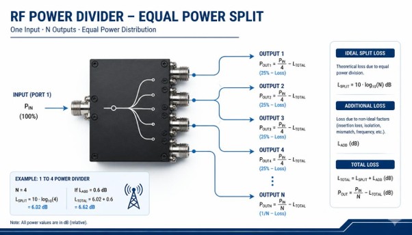
An RF power divider distributes an input signal across multiple output ports. When designing an RF system, engineers need to estimate how much power reaches each output after accounting for the theoretical power split and the losses introduced by the actual device.
Understanding power divider output power calculation helps engineers estimate signal levels, check receiver input requirements and plan RF power budgets. The calculation depends on the number of output ports and how the manufacturer specifies the divider’s insertion loss.
The following sections cover the ideal split loss, the difference between total insertion loss and excess loss, and how to calculate output power using worked examples in dBm and milliwatts.
For application-specific guidance, contact Smartcom India.
What Is an N-Way RF Power Divider?
An N-way RF power divider splits one input signal across N output ports. In an ideal equal-split divider, each output receives the same share of the input power.
For example:
- A 2-way divider distributes the input power across two outputs.
- A 4-way divider distributes the input power across four outputs.
- An 8-way divider distributes the input power across eight outputs.
- A 16-way divider distributes the input power across sixteen outputs.
As the number of output ports increases, the ideal power available at each port decreases. In a practical device, the delivered output power also depends on insertion loss, impedance matching and other electrical characteristics specified in the product datasheet.
The theoretical split is a useful starting point, but it should not be treated as the complete input-to-output loss of every divider design.
Understanding Split Loss and Insertion Loss
Two key concepts are used to calculate RF power divider output power: ideal split loss and the actual loss specified.
Ideal Split Loss
Ideal split loss is the theoretical power reduction at each output when the input power is divided equally among multiple output ports.
It can be calculated using:
Ideal Split Loss (dB) = 10 × log₁₀(N)
Here, N represents the number of output ports.
For example, an ideal 4-way divider has a split loss of approximately 6.02 dB per output. This represents the theoretical power division, without accounting for additional loss in the actual device.
Insertion Loss and Excess Loss
Insertion loss describes the reduction in signal power between the input and an output port. Depending on the specified terminology, a data may specify total input-to-output insertion loss or separately identify ideal split loss and an additional loss term.
If the datasheet specifies total insertion loss per output, calculate the output power using:
Output Power (dBm) = Input Power (dBm) − Total Insertion Loss (dB)
Do not add ideal split loss again when the specified insertion loss already represents the total input-to-output loss.
If the datasheet explicitly defines an additional loss term separately from ideal split loss, the estimated output power can be calculated as:
Output Power (dBm) = Input Power (dBm) − Ideal Split Loss (dB) − Additional Loss (dB)
Ideal Split Loss for Common N-Way Dividers
The following table shows the theoretical split loss for common equal-split configurations.
Divider Configuration | Ideal Split Loss per Output | Ideal Power per Output |
2-way | 3.01 dB | 50% |
3-way | 4.77 dB | 33.3% |
4-way | 6.02 dB | 25% |
6-way | 7.78 dB | 16.7% |
8-way | 9.03 dB | 12.5% |
16-way | 12.04 dB | 6.25% |
These values represent ideal power division only. Actual output power depends on the divider design and its specified losses.
For example, an ideal 8-way divider provides approximately one-eighth of the input power at each output. Its theoretical split loss is about 9.03 dB per output, before accounting for additional loss.
When comparing configurations for a real application, review the relevant RF power divider product information alongside the required output power and system specifications.
How to Calculate Output Power in dBm
To calculate output power, identify the input power, number of output ports and relevant loss values from the product datasheet.
For an equal-split divider where additional loss is explicitly specified separately, use:
Output Power (dBm) = Input Power (dBm) − 10 × log₁₀(N) − Additional Loss (dB)
If the datasheet instead provides total insertion loss per output, subtract that total value directly from the input power.
The following examples demonstrate the calculation method. The additional-loss values used below are illustrative assumptions.
Example 1 — 2-Way Power Divider
Assume the following values:
- Input power: 30 dBm
- Number of output ports: 2
- Ideal split loss: 3.01 dB
- Assumed additional loss: 0.4 dB
Step 1: Calculate the ideal split loss
Ideal split loss = 10 × log₁₀(2)
Ideal split loss = 3.01 dB
Step 2: Calculate the estimated output power
Output Power = 30 − 3.01 − 0.4
Output Power = 26.59 dBm per output
Step 3: Convert the result to milliwatts
Power (mW) = 10^(26.59/10)
Estimated output power ≈ 456 mW per output.
This calculation assumes equal splitting and an additional 0.4 dB loss. Actual output levels depend on the device specifications and operating conditions.
Example 2 — 4-Way Power Divider
Assume the following values:
- Input power: 20 dBm
- Number of output ports: 4
- Ideal split loss: 6.02 dB
- Assumed additional loss: 0.8 dB
Step 1: Calculate the ideal split loss
Ideal split loss = 10 × log₁₀(4)
Ideal split loss = 6.02 dB
Step 2: Calculate the estimated output power
Output Power = 20 − 6.02 − 0.8
Output Power = 13.18 dBm per output
Step 3: Convert the result to milliwatts
Power (mW) = 10^(13.18/10)
Estimated output power ≈ 20.8 mW per output.
If the device has a specified amplitude-balance tolerance, individual output levels may differ from one another. For example, subtracting 0.3 dB from the nominal estimate gives:
13.18 − 0.3 = 12.88 dBm
This corresponds to approximately 19.4 mW.
This is only an illustrative low-side calculation.
Example 3 — 8-Way Power Divider
Assume the following values:
- Input power: 10 dBm
- Number of output ports: 8
- Ideal split loss: 9.03 dB
- Assumed additional loss: 1.2 dB
Step 1: Calculate the ideal split loss
Ideal split loss = 10 × log₁₀(8)
Ideal split loss = 9.03 dB
Step 2: Calculate the estimated output power
Output Power = 10 − 9.03 − 1.2
Output Power = −0.23 dBm per output
Step 3: Convert the result to milliwatts
Power (mW) = 10^(−0.23/10)
Estimated output power ≈ 0.95 mW per output.
This example shows how increasing the number of output ports reduces the power available at each output. The assumed additional-loss value is used only to demonstrate the calculation.
Converting Output Power from dBm to Milliwatts
RF power is commonly expressed in dBm, while some applications and equipment specifications use milliwatts or watts.
To convert power from dBm to milliwatts, use:
Power (mW) = 10^(Power in dBm ÷ 10)
For example, 10 dBm equals 10 mW, while 0 dBm equals 1 mW.
The following table provides useful reference values.
Power (dBm) | Power (mW) |
30 dBm | 1,000 mW (1 W) |
20 dBm | 100 mW |
13 dBm | Approximately 20 mW |
10 dBm | 10 mW |
0 dBm | 1 mW |
−10 dBm | 0.1 mW |
Converting output power from dBm to milliwatts makes it easier to compare calculated signal levels with equipment input limits and other system requirements.
How Amplitude Balance Affects Output Power
Amplitude balance describes the variation in signal levels between output ports under specified conditions. In a practical divider, the outputs may not have the same power.
For example, a divider with a nominal calculated output of 13.18 dBm and a stated amplitude-balance value of ±0.3 dB may have output levels that differ from one another.
A simple illustrative lower-side calculation is:
13.18 − 0.3 = 12.88 dBm
This corresponds to approximately 19.4 mW.
However, amplitude balance is a relative specification, and its precise meaning depends on the manufacturer. It should not automatically be treated as an absolute output-power tolerance or a guaranteed minimum level.
When designing an RF system, check the amplitude-balance specification, insertion loss and test conditions together.
What About Resistive Power Dividers?
Not all RF power dividers use the same design. A conventional equal 2-way resistive splitter typically has approximately 6 dB of input-to-output loss per port under matched conditions.
This differs from the ideal 3.01 dB split loss of a lossless 2-way divider because a resistive design introduces additional loss.
Actual performance depends on the circuit design and operating conditions. Engineers should therefore use the specified insertion loss rather than assume that every 2-way divider has the same total loss.
When comparing divider types, consider the required frequency range, insertion loss, isolation, impedance matching, power handling and output balance.
Practical Factors to Check Before Choosing an RF Power Divider
Output-power calculations are only one part of selecting an RF divider. The following parameters can affect system performance.
1. Operating Frequency
Check that the divider supports the application’s frequency range. Performance specifications may vary across the operating band.
2. Insertion Loss
Review the specified insertion loss and confirm whether it represents total input-to-output loss or an additional loss term separate from theoretical split loss.
This distinction is essential for an accurate power budget.
3. Power Handling
Confirm the permitted input power and any per-port limits stated in the datasheet. Power handling can depend on frequency, ambient temperature, load conditions and other specified operating requirements.
Do not assume that a divider can safely handle any input power simply because its theoretical output power appears low.
4. VSWR and Isolation
Voltage Standing Wave Ratio (VSWR) indicates impedance matching. Isolation describes how much signal coupling occurs between output ports.
Both parameters can affect how a divider behaves in an RF system. Review the specified values against the needs of the application.
5. Amplitude Balance
If consistent signal levels are important, check the amplitude-balance specification and how it is defined. This matters when multiple receiver channels or signal paths must operate at comparable levels.
6. Number of Output Ports
Choose the number of outputs based on how many signal paths the system requires. A higher port count enables distribution to more destinations but also increases ideal split loss per output.
Selecting the appropriate configuration requires balancing the number of ports with the available signal power and the requirements of the connected equipment.
7. Cable and Connector Losses
The divider is only one part of the RF signal path. Cables, connectors and adapters can also introduce loss between the divider and connected equipment.
For systems where interconnect performance matters, review RF coaxial cable assemblies and account for their specified loss across the operating frequency range.
Why Choose Smartcom India for RF Power Divider Requirements?
Selecting an RF power divider requires attention to the system’s frequency, output configuration, power requirements and performance specifications.
Smartcom India offers a range of RF power dividers and combiners for applications that require RF signal distribution or combination.
When evaluating a suitable component, consider:
- Configuration: Identify the required number of output ports.
- Frequency range: Confirm compatibility with the operating band.
- Insertion loss: Calculate the expected output power using the loss definition provided in the datasheet.
- Power handling: Verify that the device supports the intended operating conditions.
- RF performance: Review applicable specifications such as VSWR, isolation and amplitude balance.
- System integration: Consider the cables, connectors and other RF components in the complete signal path.
Base the correct selection on actual application requirements and verified product specifications, not theoretical split loss alone.
Discuss Your RF Power Divider Requirements
Conclusion
Calculating output power in an N-way RF power divider starts with the ideal split loss and then accounts for the actual device loss specified.
When additional loss is explicitly specified separately, the key formula is:
Output Power (dBm) = Input Power (dBm) − 10 × log₁₀(N) − Additional Loss (dB)
If the datasheet lists total input-to-output insertion loss, subtract that total value directly instead of adding ideal split loss again.
For accurate results, verify the loss definitions and consider amplitude balance, power handling, VSWR, isolation, operating frequency, and interconnect losses when selecting a divider.
Understanding these parameters helps engineers estimate signal levels and select components that meet their RF system requirements.