
SMP vs SMA Connectors: Which Is Right for High-Frequency PCB Design?
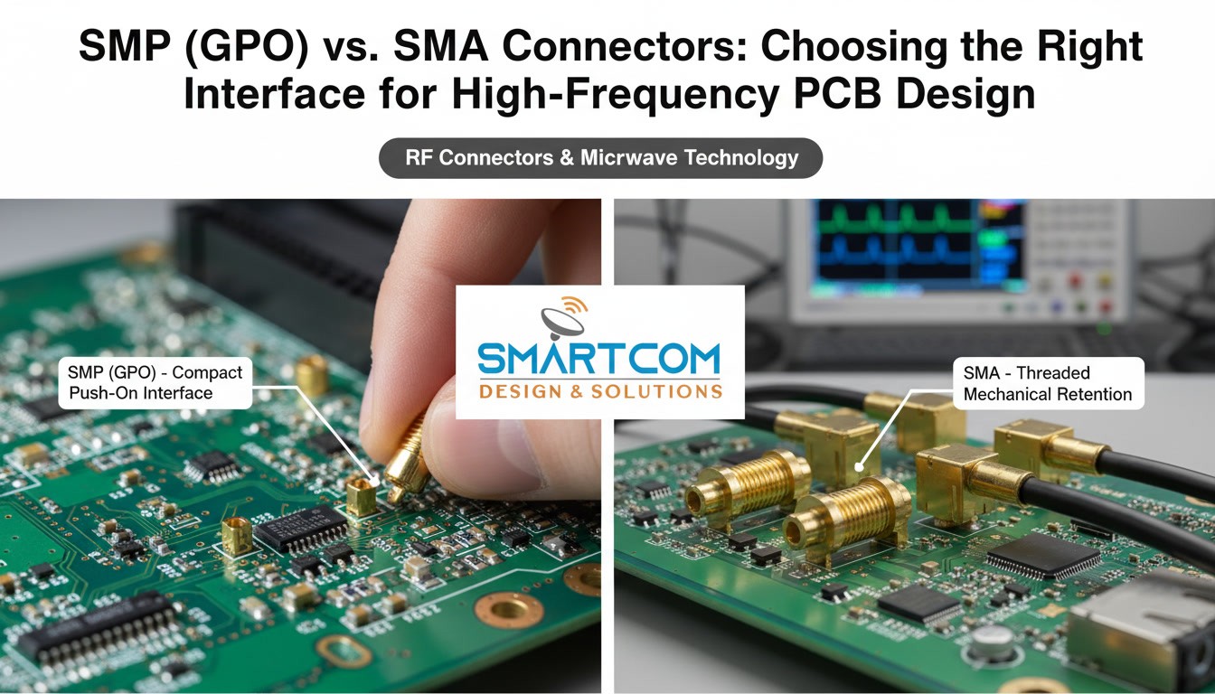
In high-frequency RF and microwave PCB design, selecting the right connector is critical. It must deliver the required electrical performance and fit the PCB layout, enclosure, assembly process, and connection method.
SMP/GPO and SMA connectors are both widely used RF interfaces, each suited to different requirements. SMP/GPO offers a compact push-on interface, ideal for high-density assemblies and limited-access applications. SMA features a threaded coupling and is commonly used for RF cables, test equipment, instrumentation, and accessible module connections.
Engineers must understand these differences when selecting high-frequency RF connectors for new or upgraded PCB designs. Smartcom offers dedicated SMP/GPO solutions, such as the SMP(GPO) Male Straight Surface Mount PCB Connector, specified for 50-ohm operation from DC to 18 GHz.
Need Help Choosing the Right RF Connector?
SMP vs SMA Connectors: Quick Comparison
Choosing between SMP and SMA requires more than considering size or frequency. Evaluate operating frequency, VSWR, insertion loss, impedance, PCB launch geometry, mechanical access, mating requirements, and connector configuration.
| Feature | SMP/GPO | SMA |
| Coupling | Push-on | Threaded |
| Form factor | Compact | Larger |
| Board density | Well suited to high-density layouts | Suitable where more space is available |
| Access | Useful where rotational access is limited | Requires access for threaded coupling |
| Typical applications | RF/microwave modules, compact PCB assemblies, aerospace, radar | RF cables, test equipment, instrumentation, modules |
| PCB mounting | Surface-mount, through-hole and other configurations | Multiple PCB and cable configurations |
| Frequency | Depends on specific part | Depends on specific part |
| Mechanical priority | Compactness and connection convenience | Threaded mechanical retention |
The table offers a general family-level comparison. Actual performance depends on the specific connector and mating configuration selected.
Smartcom provides RF connector solutions including SMP/GPO and Mini SMP configurations for RF and microwave applications.
What Is an SMP/GPO Connector?
SMP/GPO is a compact RF connector designed for applications requiring high packaging density and accessible connections.
Its push-on mating mechanism enables connection without rotating a threaded coupling nut, simplifying integration in closely spaced or limited-access RF interfaces.
SMP interfaces are often used in compact RF and microwave architectures, including blind-mate configurations. Actual blind-mate capability depends on the specific mating configuration and connector design.
For PCB applications, SMP/GPO connectors are available in surface-mount, through-hole, flange, and other configurations.
RF connector range includes SMP/GPO and Mini SMP solutions for RF and microwave applications.
Where SMP/GPO Connectors Are Used
SMP/GPO connectors are suitable for applications such as:
- High-density RF PCB assemblies
- Microwave modules
- Radar systems
- Aerospace and defence electronics
- Satellite communications
- Wireless infrastructure
- RF test and measurement equipment
- Compact RF subsystems
Select the appropriate connector based on the required electrical, mechanical, and environmental specifications.
What Is an SMA Connector?
SMA, or Sub Miniature Version A, is a widely used threaded coaxial RF connector for microwave and RF systems.
Its threaded coupling provides a secure connection, making SMA practical for accessible RF connections involving cables, instruments, test fixtures, and modules. It also supports a large ecosystem of RF cables, adapters, attenuators, and measurement equipment.
However, SMA does not have one universal frequency rating. Performance varies by connector construction, geometry, materials, manufacturing tolerances, and the manufacturer’s specifications.
Engineers should review the datasheet for the specific SMA connector rather than applying a generic frequency limit to the entire family.
Frequency Rating: Compare the Actual Connector
Frequency is a key specification, but connector families should not be assigned a single universal frequency limit.
Current product specifications illustrate this clearly:
- SMP(GPO) Male Straight Surface Mount PCB Connector: DC–18 GHz
- SMP(GPO) Male Straight Through-Hole Connector: DC–18 GHz
- SMP(GPO) Male 2-Hole Flange Connector: DC–18 GHz
- Mini SMP Male Surface Mount PCB Connector: DC–40 GHz
Engineers should not assume every SMP-family connector is suitable for 40 GHz applications.
When choosing between SMP and SMA, verify the rated frequency of the specific part number and intended mating configuration.
VSWR and Insertion Loss in High-Frequency PCB Connectors
Frequency capability alone does not determine RF connector performance.
VSWR
Voltage Standing Wave Ratio (VSWR) indicates the quality of the impedance match between the connector and the RF transmission system.
A lower VSWR generally means less reflected power at the interface.
For example, Smartcom specifies:
- SMP(GPO) surface-mount connector: VSWR ≤1.25:1 from DC–18 GHz
- SMP(GPO) through-hole connector: VSWR ≤1.25:1 from DC–18 GHz
- Mini SMP surface-mount connector: VSWR ≤1.5:1 from DC–40 GHz
These values show why connector selection should be based on actual product specifications, not just connector family names.
Insertion Loss
Insertion loss represents the signal power lost as the RF signal passes through the connector.
At microwave frequencies, connector geometry, contact quality, dielectric structure, plating, manufacturing tolerances, and PCB transition design can all influence insertion loss.
Evaluate insertion-loss performance together with the PCB launch and the rest of the RF signal path.
PCB Launch Design Matters
The connector is only one part of the RF transition.
When an RF connector is mounted to a PCB, the signal transitions from the coaxial connector to the PCB transmission line. Poorly designed transitions can cause impedance discontinuities and reflections, even if the connector has excellent specifications.
Key PCB launch considerations include:
- Transmission-line geometry
- Pad dimensions
- Ground-via placement
- PCB dielectric thickness
- Connector pin geometry
- Ground-plane structure
- Transition length
- Soldering and assembly tolerances
A connector specified as 50 ohms does not guarantee a perfect 50-ohm PCB transition.
For additional guidance on RF signal integrity and connector considerations, Explore Smartcom’s RF coaxial cables and connectors signal-integrity.
When SMP/GPO Is the Better Fit
Consider SMP/GPO when the PCB or module architecture requires compact packaging and high connection density.
Typical situations include:
- Limited PCB space
- Closely spaced RF interfaces
- Restricted rotational access
- Compact microwave modules
- High-density RF interconnects
- Internal RF subsystem connections
- Applications where push-on mating is beneficial
SMP(GPO) Male Straight Surface Mount PCB Connector is a 50-ohm connector specified for DC–18 GHz.
It is intended for RF and microwave communications, aerospace and defence, radar, satellite, test and measurement, and wireless infrastructure applications.
When SMA Is the Better Fit
SMA is suitable when a conventional threaded RF interface is preferred, and the connector is easily accessible.
Typical applications include:
- RF test equipment
- Laboratory instrumentation
- External RF cable connections
- Development and prototyping
- RF modules with accessible interfaces
- Systems using established SMA cable and adapter ecosystems
The threaded interface provides secure mechanical coupling, and the widespread use of SMA simplifies sourcing compatible cables and accessories.
As with SMP, verify that the exact SMA connector meets the application’s electrical and mechanical requirements.
Mini SMP for Compact High-Frequency Designs
Mini SMP is suitable for applications that require a compact RF interface and higher-frequency operation.
Mini SMP Male Surface Mount PCB Connector is specified for DC–40 GHz, with a 50-ohm impedance and VSWR of ≤1.5:1.
The connector is designed for applications including:
- 5G infrastructure
- Radar
- Satellite communications
- Aerospace and defence
- Automotive radar and ADAS
- RF test and measurement
- High-frequency PCB interconnections
For higher microwave frequencies, evaluate the Mini SMP specification in the context of the complete RF architecture, including the PCB launch and mating interface.
Common RF Connector Selection Mistakes
Choosing by Connector Name Alone
SMP and SMA are connector families, not complete performance specifications.
Always verify the specific part number’s frequency, VSWR, insertion loss, impedance, mounting style, and mechanical characteristics.
Assuming Every SMP Connector Is 40 GHz
SMP-family products have different ratings. Smartcom’s standard SMP(GPO) PCB products are specified to 18 GHz, while its Mini SMP surface-mount product is specified to 40 GHz.
Ignoring the PCB Transition
Design the connector and PCB launch together. Poor grounding, unsuitable pad geometry, or uncontrolled transmission-line transitions can degrade RF performance.
Overlooking Mechanical Access
The connector must fit the assembly and remain accessible for its intended mating method.
Check:
- Connector spacing
- Board-edge clearance
- Enclosure clearance
- Tool access
- Cable routing
- Mating direction
- Mechanical support
Selecting Before Defining the System Requirements
Connector selection should follow system requirements, not precede them.
Define electrical and mechanical targets before selecting the final connector.
RF Connector Selection Checklist
Before approving an RF connector for a high-frequency PCB, verify the following:
Electrical Requirements
- Operating frequency range
- Characteristic impedance
- VSWR
- Insertion loss
- Return loss
- Power requirements
Mechanical Requirements
- Connector size
- Mating mechanism
- Available access
- Mating cycle requirements
- Mechanical retention
- Environmental conditions
PCB Requirements
- Surface-mount or through-hole construction
- PCB thickness
- Pad geometry
- Ground-via arrangement
- Transmission-line configuration
- RF launch design
Assembly Requirements
- PCB assembly process
- Soldering requirements
- Rework considerations
- Inspection and testing
- Cable routing and strain management
Evaluating these factors together reduces the risk of selecting a connector that meets frequency requirements but causes issues elsewhere in the RF design.
Need Help Selecting an RF Connector?
If your application has specific frequency, PCB, packaging, or mechanical requirements, Smartcom’s engineering team can help you identify the most suitable RF interconnect solution. We offer consultation and recommendations on high-frequency RF connectors, coaxial cable assemblies, and comprehensive RF and electronic manufacturing services.
Conclusion
Choosing between SMP vs SMA connectors is ultimately a system-level decision.
SMP/GPO is ideal for compact, high-density RF and microwave architectures that need push-on mating and restricted-access connections. SMA is established for threaded RF connections, accessible cable interfaces, instrumentation, and test environments.
For high-frequency PCB design, always evaluate the specific connector, not just the connector family. Check its frequency rating, VSWR, insertion loss, impedance, mounting configuration, mechanical envelope, mating requirements, and PCB launch compatibility.
FAQ
What is the main difference between SMP and SMA connectors?
The primary difference is the coupling mechanism. SMP/GPO uses a compact push-on interface, while SMA uses threaded coupling. This difference affects packaging, accessibility, and mechanical integration.
Is SMP suitable for high-frequency PCB applications?
Yes. SMP/GPO connectors are widely used in compact RF and microwave PCB applications. Select the appropriate product based on its specified frequency and electrical performance.
Is SMP suitable for surface-mount PCBs?
Yes. Smartcom offers SMP(GPO) surface-mount PCB connectors, including a model specified for DC–18 GHz operation.
Which is better for RF testing, SMP or SMA?
The choice depends on the test setup. SMA is often convenient for accessible test connections because of its threaded coupling and broad ecosystem. SMP can be advantageous in compact fixtures or modules where space and connection density matter.