
Directional Coupler Directivity Explained
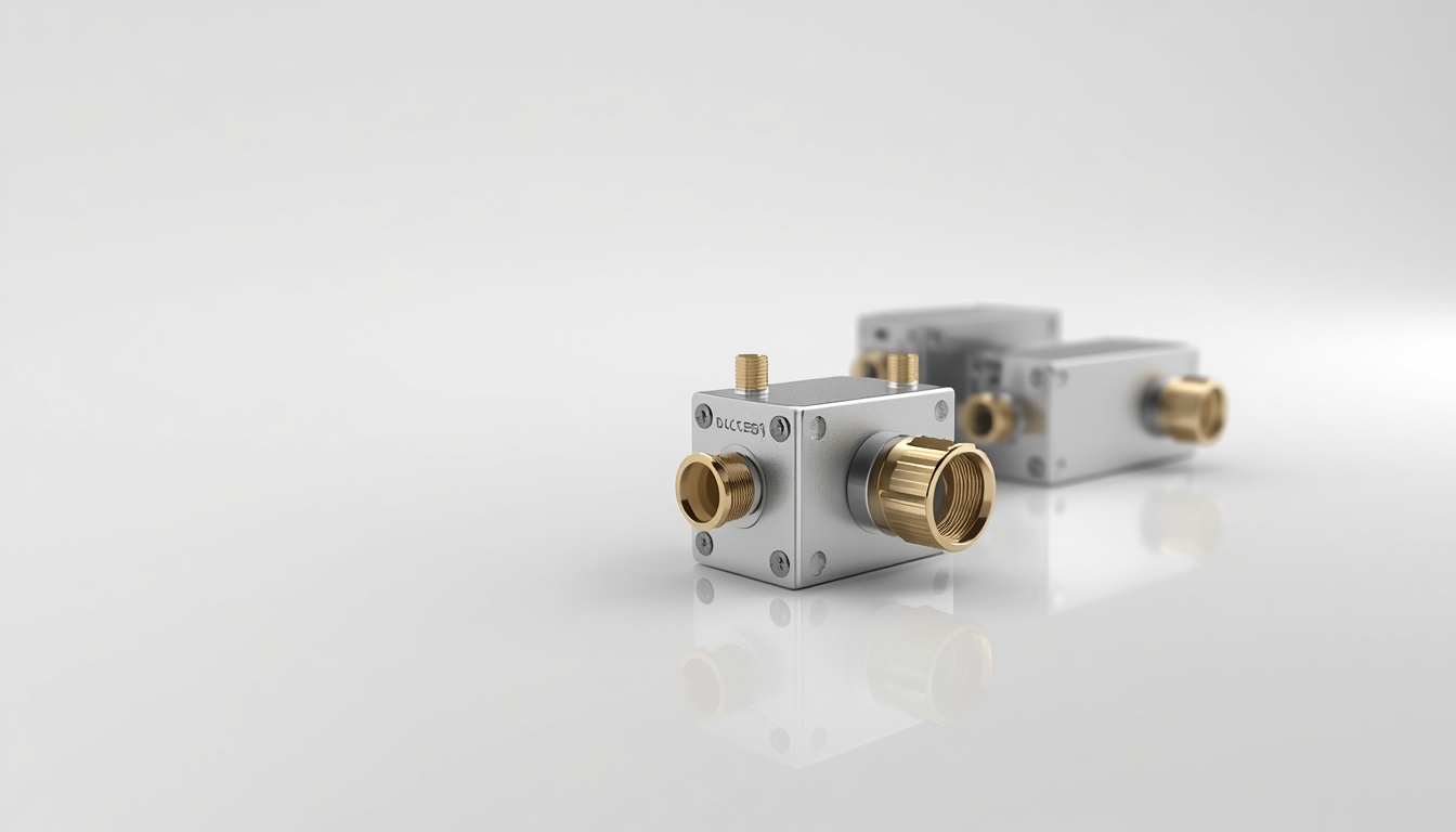
Directional Coupler Directivity Explained
A directional coupler is an important RF component used to sample signal power without interrupting the main transmission path. However, when measuring forward and reflected signals, simply knowing the coupling factor is not enough. You also need to understand directional coupler directivity.
Directivity describes how effectively a coupler distinguishes signals travelling in opposite directions. It is expressed in decibels (dB), and a higher directivity value generally indicates better separation between forward and reverse signals.
For engineers working with RF power monitoring, transmitter protection and VSWR measurement, directivity is an important specification to consider when selecting an RF component.
At Smartcom India, we provide RF and microwave solutions for communication, defence, aerospace and other demanding applications. Explore our RF Directional Couplers to compare available models, coupling factors, directivity, VSWR and power-handling specifications.
Need help selecting the right RF directional coupler for your application? Contact Smartcom India to discuss your technical requirements.
What Are the Four Ports of a Directional Coupler?
A conventional four-port directional coupler consists of four ports designed to separate and sample RF signals according to their direction of travel.
Each port has a specific function:
- Input Port: Receives the incoming RF signal from the source.
- Through Port: Allows most of the input signal to continue towards the load.
- Coupled Port: Provides a sample of the signal travelling in the intended direction.
- Isolated Port: Ideally receives very little power from the forward-travelling signal.
The isolated port is often internally terminated or externally connected to a suitable matched load, depending on the coupler design.
In a typical measurement arrangement, a directional coupler samples forward power through one coupled path and reverse power through another appropriately oriented coupling path. A dual directional coupler can provide both measurements within a single assembly.
The amount of unwanted signal at the coupled port is influenced by the coupler’s directivity.
What Is Directional Coupler Directivity?
Directional coupler directivity measures how effectively the component separates forward-travelling and reverse-travelling RF signals.
Ideally, when a signal enters the input port, the coupled port should receive the intended sample while the isolated port should receive very little signal.
In practical applications, some unwanted signal leakage occurs because of limitations in the coupler’s electrical design and construction.
Higher directivity means that the unwanted signal is smaller relative to the intended coupled signal.
This is particularly important when measuring reflected power because the forward signal is often much stronger than the reflected signal.
If the coupler cannot sufficiently reject the forward signal in the reverse measurement path, the measured reflected power may contain a significant leakage component.
Directional Coupler Directivity Formula
The standard directivity formula is:
Directivity (dB) = Isolation (dB) − Coupling Factor (dB)
Where:
- Isolation: The attenuation between the input port and the isolated port.
- Coupling Factor: The attenuation between the input port and the coupled port.
Both measurements must use the same input reference and appropriate port termination conditions.
Directivity Calculation Example
Consider an RF directional coupler with the following specifications:
- Coupling factor: 20 dB
- Isolation: 40 dB
Using the formula:
Directivity = Isolation − Coupling Factor
Directivity = 40 − 20
Directivity = 20 dB
This means the intended coupled signal is 20 dB stronger than the unwanted leakage signal at the isolated-port reference, under the specified measurement conditions.
A 20 dB difference represents a 100:1 power ratio.
Therefore, the coupler provides a measurable distinction between the intended signal and unwanted leakage.
This calculation helps engineers compare directional couplers and understand how their directivity specifications influence measurement performance.
Why Does Directivity Matter in Reflected Power Measurements?
One of the most important applications of directional coupler directivity is reflected power measurement.
When an RF signal travels toward an antenna or other load, a portion of the transmitted power may be reflected due to impedance mismatch.
This reflected signal travels in the opposite direction from the forward signal.
A directional coupler helps separate these signals so that engineers can monitor forward and reflected power independently.
However, no practical coupler provides perfect isolation.
When directivity is insufficient, some of the much stronger forward signal can leak into the reverse measurement path. This leakage can interfere with the actual reflected-power reading.
Relationship Between Directivity and VSWR
Voltage Standing Wave Ratio (VSWR) indicates the degree of impedance mismatch between connected RF components.
A higher VSWR generally indicates greater reflected power, while a lower VSWR indicates a better impedance match.
Directional couplers are commonly used in VSWR monitoring systems to sample forward and reflected power.
For reliable measurements, the coupler must have sufficient directivity for the required measurement range.
For example, suppose an engineer wants to measure a load with 20 dB return loss.
A coupler with only 20 dB directivity may not provide sufficient separation between the signal of interest and the unwanted leakage. This can make the measurement uncertain.
A higher-directivity coupler provides better separation, although the actual measurement accuracy also depends on calibration, frequency response, termination quality and the complete measurement setup.
This is why directivity should be considered when selecting components for RF directional couplers used in VSWR monitoring and transmitter protection.
Directivity vs Coupling Factor, Isolation and Insertion Loss
Directivity is closely related to other directional coupler specifications. However, each parameter describes a different aspect of performance.
Specification | What It Describes | Unit |
Coupling Factor | Amount of input power sampled at the coupled port | dB |
Directivity | Separation between intended coupling and unwanted leakage | dB |
Isolation | Attenuation from the input to the isolated port | dB |
Insertion Loss | Signal loss along the main transmission path | dB |
VSWR | Quality of impedance matching at a port | Ratio |
Understanding these specifications together helps engineers evaluate whether a directional coupler suits their application.
For example, a coupler may have a suitable coupling factor but insufficient directivity for accurate reflected-power measurements.
Similarly, check insertion loss and VSWR to ensure the component does not introduce unacceptable losses or impedance mismatches into the RF system.
How to Choose the Right Directional Coupler Directivity?
The appropriate directivity depends on how accurately you need to measure forward and reflected signals.
For basic RF power monitoring, a moderate directivity value may be sufficient. However, applications involving low reflected-power measurements, transmitter protection and precise VSWR monitoring generally require better directional separation.
Before selecting a model, consider:
- Required operating frequency and bandwidth.
- Expected forward and reflected power levels.
- Required coupling factor.
- Minimum acceptable directivity.
- VSWR and insertion-loss limits.
- Maximum input power.
- Operating temperature.
- Connector and mechanical requirements.
It is also important to consider the complete RF measurement chain. Connectors, adapters, cables, termination quality and calibration can affect the final measurement.
For additional guidance on maintaining signal integrity, read our guide to RF Coaxial Cables and Connectors. The quality of these interconnections is important when building a reliable RF measurement setup.
Why Choose Smartcom India for RF Directional Couplers?
Selecting an RF directional coupler requires more than comparing a single specification. Frequency coverage, coupling factor, directivity, power handling and VSWR must all match the intended application.
Smartcom India provides RF directional coupler solutions for applications involving signal monitoring, power measurement and RF system protection.
The product range includes unidirectional and dual-directional couplers with different frequency ranges, coupling factors, and electrical specifications.
Our product technical tables provide model-wise information to help engineers compare available options.
If you are developing an RF or microwave system, our team can help evaluate your requirements and identify a suitable solution.
Explore Smartcom RF Directional Couplers
For connector-related requirements, you can also explore our RF Connectors range.
Need assistance selecting a suitable coupler? Contact our team with your operating frequency, required coupling factor, power level and measurement requirements.
Conclusion
Directional coupler directivity is an important parameter that determines how effectively a coupler separates signals travelling in opposite directions.
Calculated as isolation minus coupling factor, directivity helps engineers evaluate a coupler’s ability to distinguish the intended sampled signal from unwanted leakage.
Higher directivity is generally preferred for reflected-power measurements and VSWR monitoring, particularly when measuring small reflected signals.
However, directivity should always be evaluated alongside coupling factor, insertion loss, VSWR, frequency range and power handling.
Understanding these specifications helps engineers choose an RF directional coupler that meets the performance requirements of their application.