
RF Cavity Filter: Working Principle, Types, Applications and Key Specifications
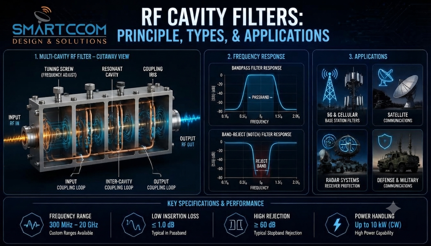
An RF cavity filter is a passive radio-frequency component designed to control specific frequencies within an RF system. It passes a defined frequency range while attenuating unwanted signals outside it. Cavity filters are essential in applications where frequency separation and interference control are critical, including cellular base stations and radar systems.
In practical RF systems, filtering works alongside other components such as RF antennas, transmission lines, amplifiers, and communication equipment. Understanding how these elements interact is important to designing a reliable signal path.
Smartcom India designs and supplies RF and wireless components for communication and specialised applications, including custom cavity filters tailored to specific band plans.
Cavity filters are often evaluated alongside related components such as diplexers and triplexers, particularly in systems that require managing multiple frequency bands on a shared path. Each component serves a distinct function.
Need a custom solution for your RF infrastructure?
What Is an RF Cavity Filter?
An RF cavity filter uses one or more resonant cavities, typically machined metal enclosures tuned to a precise frequency, to provide selective frequency control. Each cavity’s physical dimensions set its resonant frequency. For example, a cavity for the 800 MHz band is physically larger than one tuned to 2.6 GHz because resonant length scales inversely with frequency.
When an RF signal enters the filter, frequencies within the designed passband pass through with minimal loss, while frequencies outside it is attenuated. Well-designed multi-cavity units can provide 60 to 90 dB or more of out-of-band rejection, depending on the design and application. Additional cavities can be coupled together when an application needs sharper roll-off or deeper out-of-band rejection.
A cavity filter functions as a frequency gate, enabling an RF system to retain desired signals while rejecting those that could cause interference.
How Does an RF Cavity Filter Work?
The operating principle is electromagnetic resonance.
A resonant cavity stores electromagnetic energy at its designed frequency. When an incoming signal matches that frequency, the cavity responds strongly and passes it through with low loss. Signals further from resonance are increasingly attenuated, producing the characteristic band pass or band-reject curve.
The basic signal path is:
RF signal → Resonant cavity → Frequency selection → Unwanted signal attenuation → Filtered output
Multiple cavities are combined, typically ranging from two to eight in commercial base station filters, when applications require tighter bandwidth control, steeper skirts, or stronger rejection near the passband edge. The final response depends on cavity geometry, coupling method, tuning, and Q factor, which defines the sharpness of resonance.
Main Types of Cavity Filters
Bandpass Cavity Filter
Passes a defined frequency range, for example, a single operator’s downlink band, while attenuating everything outside it. It isolates one communication channel or operating band from adjacent ones.
Band-Reject (Notch) Cavity Filter
Suppresses one specific frequency or narrow range while passing frequencies outside it. It can be used when a known interferer, such as a nearby transmitter or a co-located radio, needs to be reduced without affecting the rest of the spectrum.
Multi-Cavity Filter
A multi-cavity filter combines several resonators to achieve a more precise frequency response. Adding more cavities can improve selectivity and out-of-band rejection, but it may also increase insertion loss and physical size. The design must therefore balance filtering performance with the system’s power and space requirements.
Key RF Filter Specifications
Specification | What It Means | Typical Range (Cellular/Telecom) |
Frequency range | The band the filter is designed for | 700 MHz to 6 GHz, depending on application |
Bandwidth | Width of the passband | A few MHz to tens of MHz per channel |
Insertion loss | Signal power lost passing through the filter | 0.3 to 2 dB typical for a well-matched cavity filter |
Rejection | Attenuation of out-of-band signals | 60 to 90+ dB, depending on cavity count |
Return loss / VSWR | Impedance match quality | VSWR ≤ 1.5:1, with return loss ≥ 14 dB as a common target |
Power handling | Maximum RF power the filter can sustain | From a few watts for receive-only applications to hundreds of watts for transmit applications |
These figures vary by design and vendor. They are included as reference points, not guaranteed specifications. Always confirm exact figures against the manufacturer’s datasheet for a specific part number.
Where Are RF Cavity Filters Used?
RF cavity filters are used in applications where frequency control and interference management are important.
Common applications include:
- Cellular and telecom networks, including 2G, 3G, 4G, and 5G base stations
- Wireless communication systems
- RF base stations and repeaters
- Broadcast infrastructure
- Public safety and emergency communication networks
- Microwave communication links
- Radar systems
- Satellite communication ground stations
- Defence communication systems
- RF test and measurement setups
The appropriate filtering approach depends on the frequency environment, system architecture, power level, and required rejection performance.
Why Frequency Filtering Matters
RF systems often transmit multiple signals operating on adjacent frequencies. Without effective filtering, unwanted signals may desensitise receivers, cause intermodulation interference, or significantly degrade the desired signal.
Effective filtering helps:
- Reduce unwanted frequency components.
- Improve channel separation between adjacent bands.
- Limit co-site and adjacent-channel interference.
- Protect sensitive receiver front ends from overload.
- Maintain a cleaner signal path end to end.
In advanced multi-carrier architectures, engineers often pair cavity filters with RF directional couplers to continuously monitor forward and reflected power without disrupting signal flow. Furthermore, ensuring secure, low-loss connections across the broader network layout relies heavily on choosing high-grade RF coaxial cable assemblies.
Filtering represents only one aspect of system design. Antennas, amplifiers, cabling, connectors, transmitters, and receivers all influence overall system performance.
Cavity Filter Vs Diplexer Vs Triplexer
Component | Primary Function |
Cavity filter | Selects or suppresses a specific frequency range |
Diplexer | Combines or separates two frequency bands onto or from one shared path |
Triplexer | Combines or separates three frequency bands onto or from one shared path |
A cavity filter performs frequency filtering. A diplexer allows two bands to share one antenna or feed line while keeping them isolated. A triplexer extends the same principle to three bands.
These components are not interchangeable. The right choice depends on the system’s signal path and how many frequency bands need to share it.
How to Evaluate an RF Cavity Filter?
Before selecting a cavity filter, consider the following factors:
- Required operating frequency
- Passband and bandwidth
- Acceptable insertion loss
- Required rejection level
- RF power level, including transmit or receive requirements
- Return loss and VSWR target
- Impedance compatibility, typically 50Ω
- Connector type and interface requirements
- Physical size and mounting constraints
- Operating environment, including temperature, humidity, vibration, and outdoor exposure
Considering all these factors together provides a more reliable basis for filter selection than focusing solely on frequency.
Why Choose Smartcom India?
Technical requirements for RF filtering vary significantly between applications. Frequency plan, bandwidth, power level, environment, and mechanical constraints can all influence the final design.
Smartcom India adopts a system-level approach to help ensure the selected component integrates effectively within the complete RF chain.
Ready to optimize your RF signal path?
Conclusion
An RF cavity filter employs electromagnetic resonance to achieve precise frequency selection within an RF system. It reduces unwanted signals and improves channel separation.
Proper evaluation requires consideration of parameters such as insertion loss, rejection, VSWR, and power handling, as well as the filter’s role within the complete signal chain rather than as an isolated component.
FAQ
What is an RF cavity filter used for?
It passes a required frequency range while reducing unwanted signals outside it. It is commonly used wherever frequency separation and interference control matter, such as cellular base stations and radar systems.
How does an RF cavity filter work?
It works through electromagnetic resonance. Resonant cavities respond strongly to their designed frequency and attenuate frequencies outside that response.
What are the important cavity filter specifications?
Frequency range, bandwidth, insertion loss, rejection, return loss, VSWR, and power handling are the key parameters to check against a datasheet.
What’s the difference between a cavity filter and a diplexer?
A cavity filter selects or rejects a frequency range. A diplexer combines or separates two frequency bands so they can share one antenna or feed line.
Does every RF system need a cavity filter?
No. It depends on the frequency environment, interference risk, bandwidth needs, power level, and overall system architecture.