
What Is an RF Diplexer? Working Principle, Types and Applications
An RF system may need to transmit or receive signals across different frequency bands while using a shared antenna or transmission path. Managing these signals requires components that separate the required frequency bands and limit unwanted interaction between them. An RF diplexer is one such component.
Understanding the RF diplexer working principle helps engineers evaluate its role in wireless communication equipment, antenna systems and other radio-frequency applications. The correct configuration depends on the frequency bands, isolation, insertion loss, power handling and other system requirements.
Connect with smartcom to accelerate your next project with custom RF and microwave solutions.
What Is an RF Diplexer?
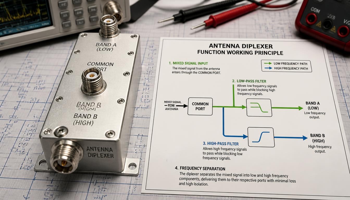
An RF diplexer is a three-port radio-frequency component that combines two frequency bands onto a shared path or separates two frequency bands arriving through a common path.
A typical diplexer has one common port and two frequency-selective ports. Each branch passes its intended frequency band while attenuating signals outside that band.
For example, a system may need to connect two radio-frequency bands to one antenna feed. A well-designed diplexer can route each band through the appropriate branch without needing a separate antenna feed for every band.
A diplexer is not the same as a basic power divider. A power divider splits a signal between multiple ports, while a diplexer uses frequency-selective paths to separate bands.
How Does an RF Diplexer Work?
An RF diplexer works based on frequency-selective filtering.
Each diplexer branch is designed for a specific frequency range. Signals within the intended passband pass through that branch, while signals outside the passband are attenuated by the filter design.
During reception, signals entering the common port can be directed towards the relevant frequency-band ports. During transmission, signals from two frequency-band paths can be combined onto a shared port when the component is designed and rated for that use.
Actual performance depends on the frequency plan, filter topology, impedance matching, and interaction between the branches.
Main Parts of an RF Diplexer
Common Port
The common port connects to the shared antenna, feed line or RF system interface.
Frequency-Selective Branches
Each branch passes its intended frequency range and suppresses unwanted frequencies as designed.
Filter Network
The internal filter network establishes the passband, rejection, insertion loss and isolation characteristics. Cavity-based designs may use resonant metal structures to achieve the required frequency response.
Types of RF Diplexers
Cavity Diplexers
A cavity diplexer uses resonant cavity structures to provide frequency-selective paths. These designs suit applications requiring specific combinations of frequency range, power handling, selectivity, and isolation.
Coaxial Diplexers
A coaxial diplexer uses coaxial RF interfaces and a suitable internal filtering arrangement. Compatibility depends on the frequency range, impedance, connector type and electrical specifications.
Custom-Frequency Diplexers
A custom diplexer may be required when standard frequency combinations do not meet the system’s operating requirements. Engineers must define the passbands, isolation, insertion loss, power levels, and mechanical constraints before selecting a configuration.
Important RF Diplexer Specifications
Frequency Range and Bandwidth
The operating frequency range identifies where the diplexer is designed to work. Each branch must support the intended band and bandwidth.
Insertion Loss
Insertion loss describes the signal power lost as it passes through the relevant path. Lower insertion loss is often desirable, but the acceptable value depends on the application and system link budget.
Isolation
Isolation measures how effectively signals are separated between relevant ports or frequency paths. Adequate isolation helps limit unwanted coupling between bands.
VSWR and Return Loss
These parameters describe impedance matching and reflected power. Poor matching can cause reflections that affect the wider RF system.
Power Handling
The diplexer must be rated for the expected RF power, including the relevant operating conditions and any applicable peak-power requirements.
Evaluate specifications together rather than choosing a component based on frequency alone.
Where Are RF Diplexers Used?
RF diplexer applications include systems that need two frequency bands to share a common RF path.
Examples include:
- Shared-antenna wireless communication systems
- Telecom infrastructure
- Multi-band radio equipment
- RF transmission and reception systems
- Selected microwave and satellite communication applications
- Test systems that require frequency-selective signal paths
The appropriate design depends on the frequencies involved and the application’s electrical, mechanical, and environmental requirements.
How to Select an RF Diplexer
Before choosing a diplexer, define the system requirements:
- Identify both operating frequency bands.
- Specify the required bandwidth of each branch.
- Establish acceptable insertion loss and required isolation.
- Confirm impedance and connector compatibility.
- Determine continuous and peak RF power requirements.
- Review VSWR, return loss and out-of-band rejection.
- Check physical dimensions and environmental conditions.
- Confirm that the component supports the intended transmit or receive configuration.
These requirements help engineers compare available components and identify whether a custom design is needed.
Explore RF Diplexer Options with Smartcom India
Smartcom India lists RF diplexers, RF triplexers, and cavity filters for RF system applications.
Review the RF cavity filters, diplexers and triplexers to examine the published options. For a technical enquiry, prepare the required frequency bands, bandwidth, isolation, insertion loss, power rating and connector details.
Ready to optimize your RF system?
Contact Smartcom today for a custom technical consultation
Conclusion
An RF diplexer helps two frequency bands share a common RF path while maintaining frequency-selective routing. Understanding its operating principle and specifications helps engineers choose a configuration suited to their system.
Engineers should consider frequency requirements, isolation, insertion loss, impedance matching, and power handling before selecting a component.